


Opening Global Settings
Basic settings for timber design are managed in the “Global Settings” dialog box. This dialog box is essentially independent of the standard that you selected in the model base data. However, the default values may differ from each other.
You can access the global settings using one of the following ways:
- Shortcut menu in the “Timber Design” navigator entry
- Button
 in the toolbar of the Timber Design tables

Global Settings

Click the
![]() button to restore the default settings for the standard.
button to restore the default settings for the standard.
Configurations to Design
By default, all available configurations are analyzed. However, if you do not want to perform a serviceability analysis, for example, deactivate the “Serviceability” option. This prevents serviceability limit states from being designed; the input data for the timber design is reduced accordingly.
Design situations assigned to a deactivated configuration are not considered in the design process. The assignment of design situations is defined in the table Design Situations.
Smoothing Settings
The smoothing settings are relevant for the design of surfaces. The stresses are calculated for the nodes of the FE mesh and then smoothed using an interpolation method. This allows you to see a continuous distribution of the results in the graphic.
The following smoothing settings can be selected from the list:
- Constant within mesh elements
- Non-continuous
- Continuous within surfaces
- Continuous within surface sets, otherwise within surfaces (default)
- Continuous within all surfaces
The individual options are described in the chapter Result Smoothing of the RFEM manual.
Analysis Methods
In this section, you can control how the internal forces from load and response combinations are transferred to the design. The list provides three analysis methods to select from.
- Enumeration Method
All load and response combinations in a design situation are calculated individually. This approach generally provides the most accurate results, but may result in longer calculation times.
- Envelope Method
The enveloping internal forces (max/min) of all load and response combinations in a design situation are calculated first. The design checks are then performed using these internal forces. Compared to the enumeration method, this reduces the calculation time. However, it cannot be guaranteed that all possible combinations are covered.
- Mixed Method
This approach provides a compromise between the other two methods: For members and surfaces, you can specify an upper limit for the variants of a design scenario that are to be designed using the enumeration method. Once the number of load and response combinations exceeds this limit, the design is performed using the envelope method.
Checking Slenderness Ratios of Member/Member Set
As part of the timber design, the slenderness ratios of members and member sets subjected to tension, compression, or bending are also checked. Here, you can specify the limit values (λlim, RB, and so on.). If effective lengths are defined for the segments of the members or member sets to be designed, these are taken into account when performing the calculation of the slenderness ratios. The results are displayed in the result tables for slenderness ratios.
Optimization – Maximum Allowable Design Ratio
The add-on can perform an optimization for standardized cross-sections (see the chapter Cross-Sections). When checking the possible variants, the variant's design ratio is compared to the maximum value defined here.
Storing Results
For models containing several thousand objects, the result files can become very large. The list provides two options that allow you to control how the design results are saved.
- By Location or By Mesh Node/Grid Point
The maximum results are saved for all stress points of the members or FE mesh nodes and grid points of the surfaces. This affects the file size accordingly.
- By Object
Only the maximum results for each member or surface are saved. The result file becomes significantly smaller.
Smoothing Settings for Result Beam Calculation
A result beam integrates the internal forces of members, surfaces, or solids. For the design in the add-on, you can control which smoothing setting is applied when integrating the results. The following options are available in the list:
- Constant in mesh elements
- Not continuous
- Continuous within surfaces or solid bodies
- Continuous within surface sets, otherwise within surfaces
- Continuous within all surfaces or solids
The individual options are described in the chapter Result Smoothing of the RFEM 6 manual.
Display Results
If you select the “Show results by design situation” check box, the results will be displayed separately in the tables for each design situation.
Calculate Results
The results for the surfaces are based on the results at the FEA mesh nodes, which are processed for graphical output taking into account the smoothing settings. As in the case of the results of the structural analysis, you can select in the Navigator – Results whether the values are displayed at the FE mesh nodes or at the grid points of the surfaces (see the chapter grid-mesh Result Values on Surfaces of the RFEM manual).
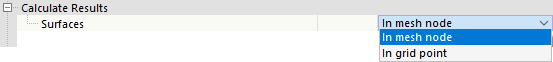
Both options in the list affect the results displayed in the tables and in the design check details: They allow you to control whether the values of the mesh nodes or the grid points are displayed. The surface grid represents an output independent of the FE mesh, consisting of result points at regular intervals (see the chapter Surfaces of the RFEM manual). These options do not affect the graphical results.
Reference Plane of Surface for Solver
The “Shift reference plane in case of fire” function allows the surface plane used for fire resistance design to be shifted back to its original location (“zero plane”). This is achieved using internal surface eccentricities, thereby restoring the reference to the original location of the surface.
Life Cycle of Results
As soon as you make a change to the input data, the results of the timber design are cleared. This ensures that the design is based on the correct boundary conditions. In some cases, however, it may be appropriate to retain the results (for example, to make a change in a complex model that does not affect the design). To do this, deactivate the check box. If you make a change, no recalculation will be performed. All results affected by this change will then be displayed in red. They may no longer be valid. They will only be updated after a recalculation.
Surfaces | Beam Panels | Components to Design
The last category is only relevant if the Multilayer Surfaces add-on has been activated in the model base data and there are surfaces of the Beam Panel thickness type available in the model.
You can use the check boxes to control which components should be checked during the design of beam panels:
- Beams
- Sheathing
- Connectors
For example, if you only want to obtain design checks for the connectors and omit the design of the framing members and studs, deactivate the irrelevant component groups here.