Question
I have entered a line hinge in the center of a surface, and the bending moment is not equal to zero at the line hinge. Why?
Answer:
If the line hinge has been defined correctly, the problem may lie in the incorrect support definition.
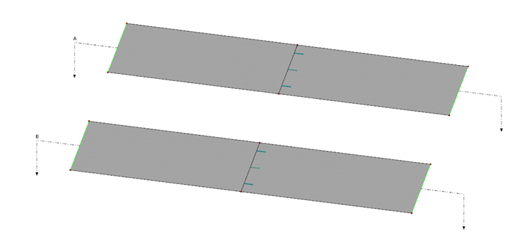
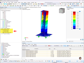
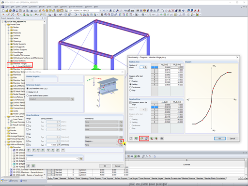
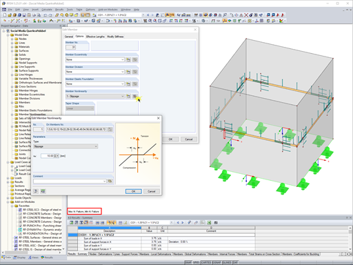
Although the structural system (see Image 01) would seem to be the same, there is a moment in the mid-span resulting from the determination of internal forces on the surface.
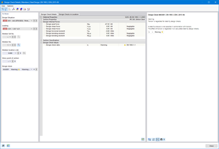
In the present case, the cause can be derived from the error message after the load case calculation.
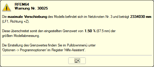
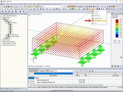
There are very large deformations resulting in the bottom structure, so this already indicates an incorrect support of the surface.
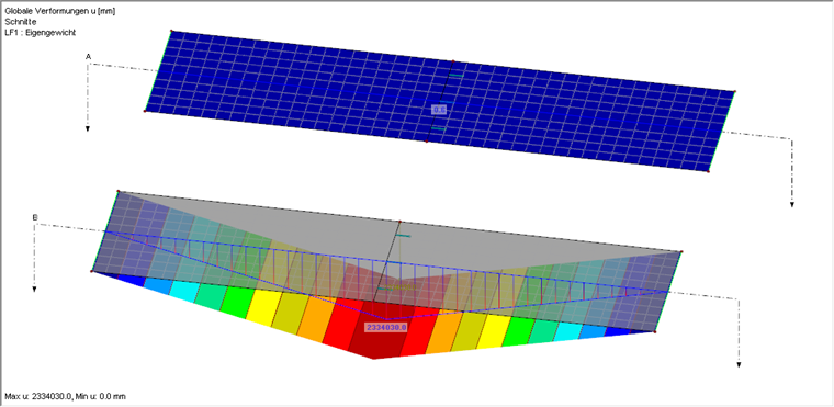
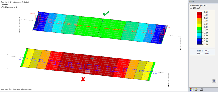
When checking the line supports, it becomes clear that the bottom structure is rotated about the global Y-axis due to the missing restraint. This ultimately leads to the inconclusive distribution of internal forces in the basic internal force m-x.
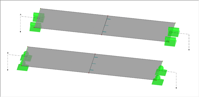
If you adjust the line support, you will get the expected result.
Do you have any questions?
In RF-/FOUNDATION Pro, the user can freely select the proportion of the relieving soil pressure by means of the factor kred.
In RFEM 5 and RSTAB 8, it is possible to assign nonlinearities to member hinges. In addition to the nonlinearities "Fixed if" and "Partial activity", you can select "Diagram". If you select the "Diagram" option, you have to specify the according settings for the activity of the member hinge. For the individual definition points, it is necessary to specify the abscissa and ordinate values (deformations or rotations and the according internal forces) that define the hinge.
In RF-/FOUNDATION Pro, you can also consider the concrete cover for the foundation according to EN 1992-1-1.
RFEM 5 allows you to use many different member nonlinearities for designing a model. In the following text, we look at an example of the use of the "slippage" member nonlinearity. The example is a simplified model of a concrete manhole with a square plan view.
The results of solid stresses can be displayed as colored 3D points in the finite elements.
Use the "Independent mesh preferred" option in the FE mesh settings to create an independent FE mesh for the integrated objects. This allows you to generate a significantly more detailed and precise FE mesh for individual objects that are integrated into one another.
In the "Edit Section" dialog box, you can display the buckling shapes of the Finite Strip Method (FSM) as a 3D graphic.
In RFEM 6 and RSTAB 9, you have the option to enter "Visual Objects" as guide objects. You can import the file formats 3ds, stl, and obj.
These objects allow you to create a better reference to the dimensions.
Recommended Products for You