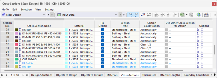
The Sections table in the "Steel Design" category lists all cross-sections you have created in the model.
Allowable Cross-Sections
The steel design is possible for four cross-section types. The font color of the cross-section gives you the information about the utilization and validity of the cross-section. The colors have the following meaning:
- Red = a cross-section not suitable for the design in the active add-on
- Blue = a cross-section not used in the entire model
- Gray = objects with this cross-section are not selected for design in the active add-on
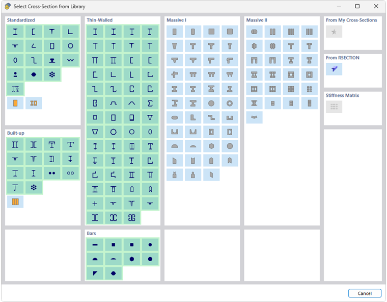
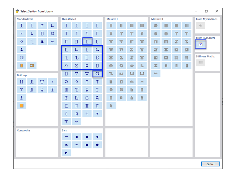
Furthermore, thin-walled cross-sections can be designed using the cross-section property program RSECTION (see the section RSECTION Cross-Sections). The categories of the individual cross-sections are specified in the "Section Type" column in the table.
Objects with an invalid cross-section are not included in the design, even if the “To Design” option is activated for this cross-section. They are automatically displayed as “Not valid / Deactivated” in the Objects to Design table.
Removing Cross-Sections from Design
For a valid cross-sections, you can exclude all objects with this cross-section assigned from the design by clearing the "To Design" check box. These objects are thus classified as "Not Valid / Deactivated" in the Objects to Design table and not analyzed in the design.
Cross-Section Classification (for EN 1993, NTC, and SIA 263)
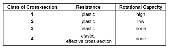
The cross-section classification enables considering the limitation of load-bearing capacity and rotational capacity due to local buckling of cross-section parts for some standards. If there are single panels entered for a cross-section, automatic cross-section classification is activated by default. The program checks c/t ratios of the cross-section parts subjected to compression and classifies the cross-section into cross-section classes 1 through 4.
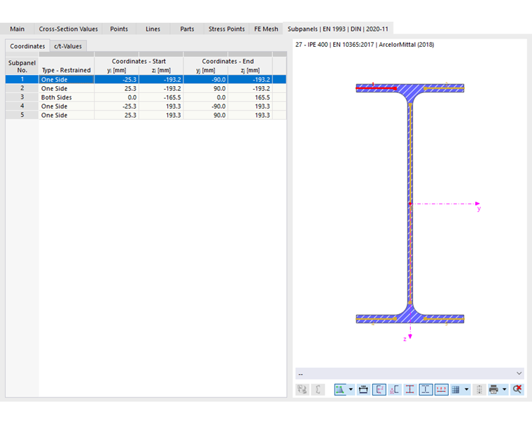
You can also specify the cross-section class manually in the table column list.
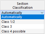
- Class 1/2: The design is performed with the plastic section resistances without further checking the c/t parts.
- Class 3: Elastic design is performed with no additional check of the local buckling
- Class 4 possible: During the design, it is checked whether the effective section properties have to be taken into account. Depending on the result, the cross-section is classified in Class 3 or Class 4 and designed accordingly.
Buckling Curves (for EN 1993, NTC, and SIA 263)
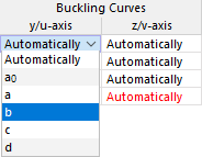
According to some standards, buckling curves describe the reduction factor χ as a function of the related relative slenderness ratio λ̄. This factor reduces the load capacity of a member subjected to a compressive force. Buckling curves account for the imperfections of real members (such as geometric initial bows and internal stresses arising from rolling or welding) via the imperfection coefficient α. For example, Table 6.1 in [1] lists the buckling curves a0, a, b, c, and d with α = 0.13 / 0.21 / 0.34 / 0.49 / 0.76. Table 6.2 specifies which buckling curve applies, depending on the cross-section shape, manufacturing method (rolled or welded), h/b ratio, flange thickness, buckling direction (y-y or z-z), and steel grade.
The buckling curves stored with the cross-section parameters are automatically used for the design. However, you can also specify the effective length of the buckling manually.
Design of Cold-Formed Sections (for EN 1993 and AISC)
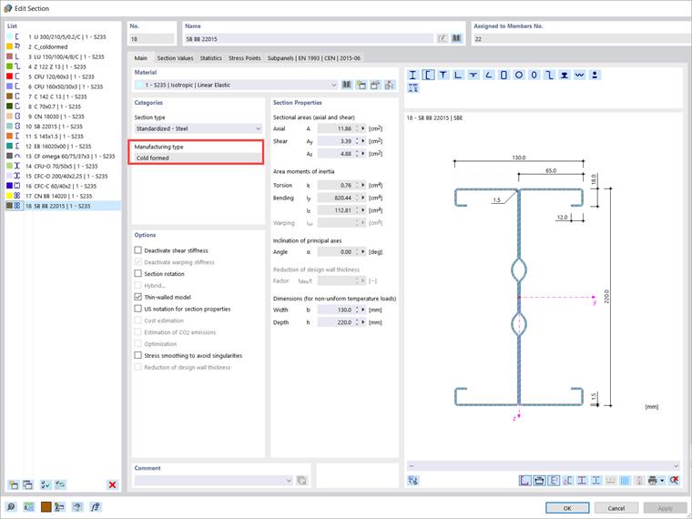
Cold-formed sections usually require special design checks with regard to the local buckling and cross-section stability. In the case of a cross-section with the "cold-formed" manufacturing type and the EN 1993 design standard, the objects with this cross-section are designed automatically according to EN 1993‑1‑3 [1] (except for cold-formed hollow sections). In the case of the AISC 360 standard, the cold-formed sections are designed according to AISI S100 [2].
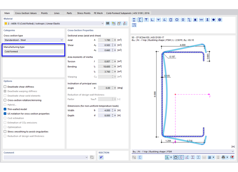
For other design standards, no special design of cold-formed sections is currently implemented.
Adjusting Cross-Sections
If necessary, you can adjust the properties of a cross-section in the editing dialog box. To do this, double-click in the cross-section line or click the
 button in the table toolbar.
The “Options” table column includes icons for settings or modified values (see the image Table "Cross-Sections"). They allow for a quick overview of the cross-sections used. The
 icon, for example, is assigned to all cross-sections that are calculated according to thin-walled theory.
Notes on Stress Determination
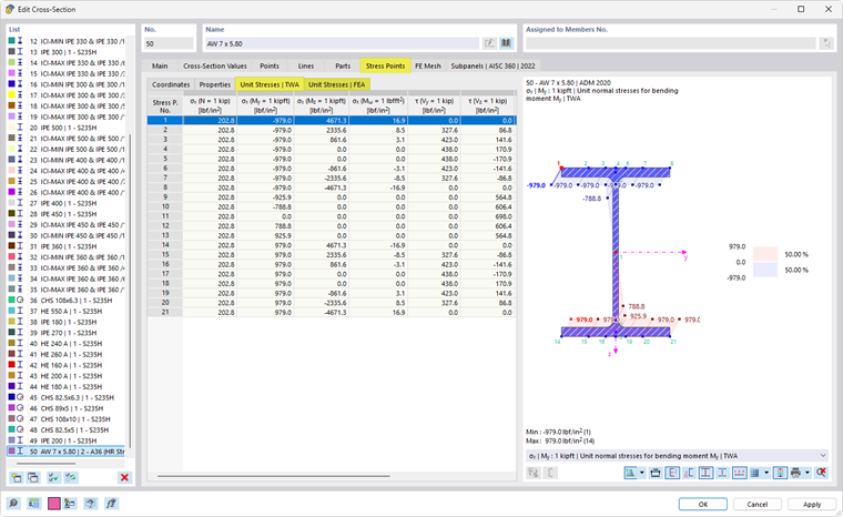
The stress-based design checks of a cross-section are based on the selected calculation theory in the cross-section. If you activate the “Thin-walled model” for the cross-section, both the cross-section properties and the stresses used for design are determined according to the thin-walled analysis (“TWA”). If this option is not activated, the cross-section properties and stresses are determined based on an FEM solution.
The unit stresses for the respective stress determination provide a good basis for understanding the stress values used in a design. You can check these in the cross-section editing dialog box.
RSECTION Cross-Sections
The options for the design of cross-sections in the RSECTION program depend on the modeling of the cross-section: If the cross-section contains elements, single panels (cross-section parts) are automatically generated, which allow for the calculation of the effective cross-section. However, if the cross-section is defined by parts without elements, single panels cannot be generated. Automatic cross-section classification is then not possible.
Using Other Cross-Section for Design
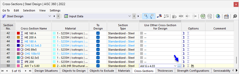
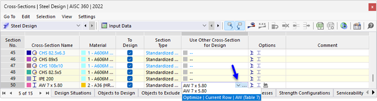
You can use a different cross-section for the design than for the RFEM/RSTAB calculation: To do this, click in the corresponding row of the “Use Other Section for Design” column in the table. You can then import a cross-section from the library using the
 button.
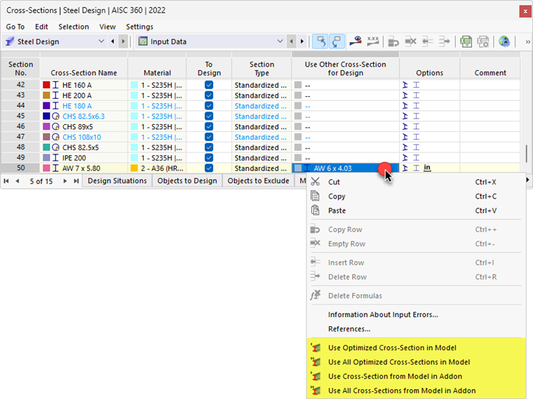
If another cross-section is stored in the column, additional options are available in the shortcut menu. You can use these options to transfer the new cross-section to RFEM or RSTAB so that it is also used in the structural analysis. It is also possible to import the original cross-section back into the table.
Cross-Section Optimization
The Steel Design add-on provides the option to optimize standard cross-sections. Using this simplified optimization, the program searches for the smallest possible cross-section within the same cross-section series that fulfills all design checks with a design criterion smaller than the maximum allowable design ratio specified in the Global Settings dialog box.
To optimize a cross-section, click the corresponding cell in the "Use Other Section for Design" column in the table. Then, select the "Optimize" option from the list.
For a parametric cross-section, the editing dialog box for the cross-section appears. In the “Optimization | Steel Design” tab, you can specify the parameters for optimization.

In the “Geometry” column, select the parameter(s) you want to change. You can then enter the lower and upper limits for the parameter in the “Min” and “Max” columns. The “Step” controls the interval in which the dimensions of the parameter vary during the optimization process. If you want to “Maintain aspect ratios,” select the corresponding check box and specify two parameters for the optimization of external dimensions.
The same conditions apply to cross-section optimization as when using a different cross-section (see above). The design checks are performed for all cross-section variants with the internal forces of the structural analysis. The optimal variant is then displayed in the table column. The effects of the modified cross-section on the stiffnesses and internal forces in the model are not taken into account. Therefore, use the options in the shortcut menu to transfer the optimized cross-sections to the RFEM/RSTAB model (see the image Shortcut Menu with Export or Import Options).
Comprehensive structural optimization is possible using the Model Optimization add-on.