


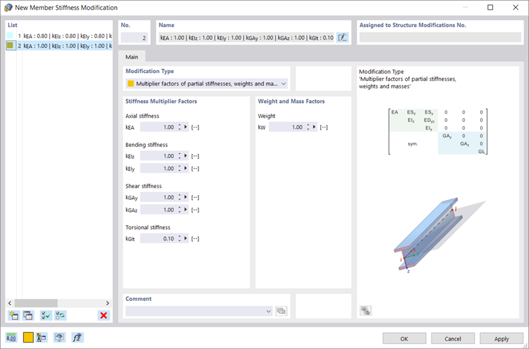
A member stiffness modification offers various options to affect the stiffness of members. This type can then be assigned to specific members in a structure modification (see the image Defining Stiffness Modification for Members).
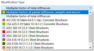
Modification Type
Various types are available for selection in the list. The other sections of the dialog box match the modification type.
Multiplier Factors
You can adjust the stiffness in two ways using the "Multiplier Factors":
- Total stiffnesses: All elements of the stiffness matrix are uniformly multiplied by the factor "k".
- Partial stiffnesses, weights, and masses: The elements of the stiffness matrix and the weight can be modified by specific factors.
The image New Member Stiffness Modification shows how the torsional stiffness GIt is reduced to 10%.
Settings
For US and Canadian standards, there are some modification options to apply stiffness factors in compliance with the standards.
ACI 318-19 / CSA A23.3
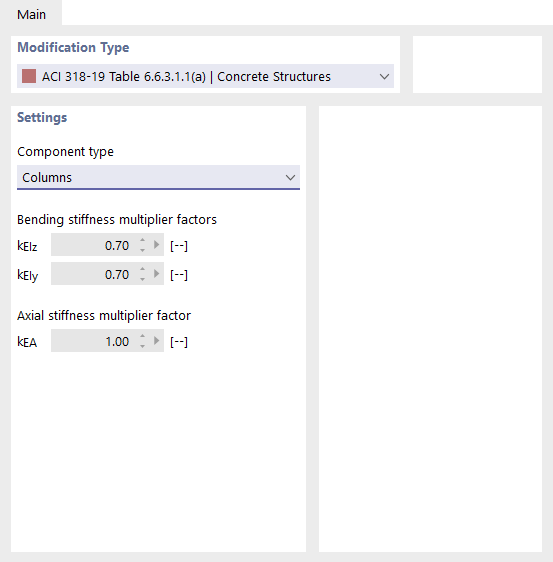
Select the "Component Type" from the list:
- Columns
- Walls uncracked
- Walls cracked
- Beams
- Flat plates and flat slabs
The factors for determining bending stiffness and axial stiffness are set according to the standard specifications.
AISC 360-16 / CSA S16
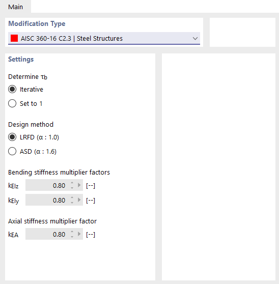
Define the parameters to "Determine τb" and the "Design method". When determining internal forces and moments, it is necessary to consider the factor τb for all members whose bending stiffness have a share in the stability of the structure. This coefficient depends on the axial force in the member: The larger the axial force, the larger τb is.
If τb is determined iteratively according to AISC, you have to specify the design method—LRFD or ASD. Then, RFEM calculates the factor according to Equation (C2‑2a) or (C2‑2b) in several steps until convergence is reached. Independent of the factor τb, the reduction factor 0.8 is applied to all members for bending and axial stiffnesses, as required in AISC 360‑10.