Fire Resistance Configurations are currently available for the steel design according to the following standards:
- EN 1993
- NTC
- GB 50017
These configurations control the specifications according to which the fire resistance design of an object is performed ("hot design"). Here, you can specify the parameters for determining the steel temperature that is applied for the fire resistance design.
EN 1993 / NTC

The design for the accidental situation of fire exposure is carried out in principle like the design for the ultimate limit state. However, due to the increased final steel temperature, the material properties are reduced accordingly. The relevant regulations can be found, for example, in EN 1993-1-2 [1].
Definition of Temperature
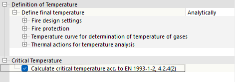
Via the list (see image New Fire Resistance Configuration), you have two options for defining the final temperature:
- Analytical: The steel temperature at a specific time is determined based on the gas temperature according to various fire curves.
- Manual: You can specify the final steel temperature user-defined.
Analytical Determination
In the Settings for Fire Design category, specify the required fire resistance duration tfi,req and the time interval Δt for the temperature calculation.
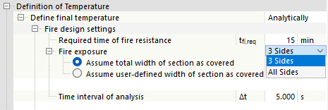
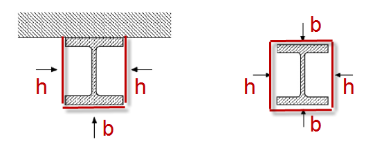
A cross-section can be assumed as exposed to fire on all sides or on three sides for the design. This affects the calculation of the component temperature and the determination of design coefficients according to [1]. For three-sided fire exposure, you can either define the width of the protected side user-defined or use the automatic determination: In this case, it is assumed simplified that one side over the entire width of the cross-section is protected and not exposed to fire (typical application case for a beam with a concrete slab on top).
If the cross-section is protected by specific measures against fire exposure, select the 'Define Fire Protection Parameters' check box in the Fire Protection category.
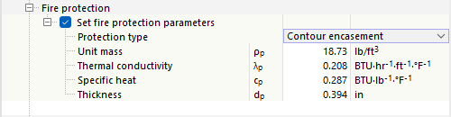
Two options are available for selection in the 'Protection Type' list:
- Contour following cladding: Cladding of constant thickness adapted to the cross-section contour (e.g., plaster or board cladding)
- Box cladding: Rectangular external cladding of the cross-section
Specify the material properties and the thickness of the cladding. The temperature is determined considering these parameters according to [1] 4.2.5.2. According to [1], only board materials and plasters can be used as fire protection materials. A design with this scheme is not permitted for intumescent coatings or reactive coatings, as these claddings change their properties depending on the temperature.
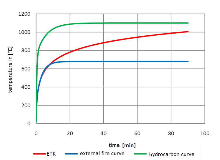
In the Temperature Curve for Determining the Gas Temperature category, specify which temperature curve is to be used:
- Standard temperature-time curve
- External fire curve
- Hydrocarbon fire curve
In the design details, you can display the temperature curve in the Temperature-Time Diagram.
In the Thermal Actions for Temperature Analysis section, the coefficients used for the temperature calculation are preset according to the recommended values of EN 1993-1-2 [1] and EN 1991-1-2 [2]. You can adjust these if necessary.
You can consider the beneficial effect of hot-dip galvanizing when determining the steel temperature by adjusting the surface emissivity. To do this, activate the 'Galvanized surface of carbon steel member' check box. When determining the steel temperature, the lower emissivity of the galvanized surface εm,lim is taken into account up to the set limit temperature tlim. At higher temperatures, the surface emissivity of the carbon steel εm is then applied. This procedure corresponds to the specifications of the DASt Guideline 027 Determination of the Component Temperature of Hot-Dip Galvanized Steel Components in Case of Fire, whose values are preset.
Manual Definition
If you want to specify the steel temperature directly, select the Manual option from the list (see image New Fire Resistance Configuration). Then enter the final material temperature Θa for which the fire resistance design is to be performed.
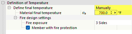
For the determination of the coefficient k1 according to [1] 4.3.3 for non-uniform temperature distribution in the bending check, information on the fire exposure (all sides or three sides, if necessary with fire protection measures) is also required for the manual definition of the temperature. The coefficient k2 for a non-uniform temperature distribution along the beam length is assumed on the safe side as 1.0 for all cases.
Critical Temperature
In addition to the pure fire resistance design, the program also offers the option to determine the critical temperature for the cross-section checks. This value represents the maximum temperature that may be reached so that the member or member set still resists the actions. To do this, select the Calculate critical temperature according to EN 1993-1-2, 4.2.4(2) check box.
After the calculation, the critical temperature Θa,cr is output for each design in the Design Details. As mentioned, this option is not available for stability analyses.

Notes on Fire Resistance Design
The basic settings for the ultimate limit state checks (for example, elastic or plastic check) or for the stability analyses (for example, load application point) are also adopted for the fire resistance designs from the Ultimate Configurations of the object. The utilization limits defined there for ignoring internal forces and stresses also apply to the fire resistance design.
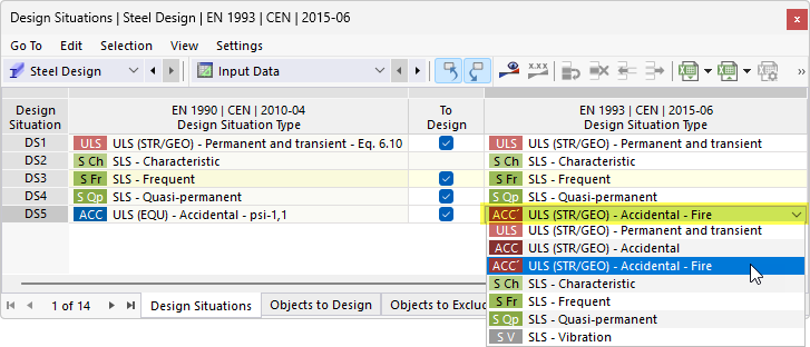
Design Situation
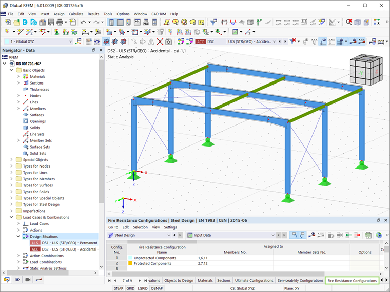
The fire resistance designs according to EN 1993-1-2 [1] are only performed for design situations that are assigned the type 'ACC' ULS (STR/GEO) - Accidental - Fire' for the steel design in the input table of the Design Situations.
Since the General Method for stability analyses according to EN 1993-1-1 [2] 6.3.4 is not applicable according to the standard for fire resistance designs, the stability analyses are performed using the equivalent member method according to EN 1993-1-2 [1] 4.2.3. The assigned Effective Lengths are also used for the fire resistance design. There is no explicit reduction of the modulus of elasticity: The reduction is considered in the stability analyses via the reduction factors according to [1].
You can specify the steel temperature in the form of temperature loads for the analysis (see chapter Member Loads of the RFEM manual).
Local buckling of slender cross-section parts can also represent a governing failure mode in case of fire. Checks for Class 4 cross-sections are performed in the Steel Design add-on according to [1] Annex E. The check against shear buckling of slender web plates is currently not implemented in the fire resistance designs.