


The Members | Stability tab is available if the 'Perform stability analysis' check box is selected in the Members | Basis tab. Here, you can make further settings for the stability analyses.
The 'Design parameters' are divided into several categories, which vary depending on the design standard.
EN 1993
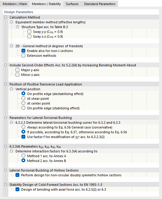
Calculation method
For the design according to the Equivalent member method according to Sections 6.3.1 to 6.3.3, it is necessary to define effective lengths. The 'Structure type according to Table B.3' is relevant for members with buckling in the form of lateral displacement. With the two check boxes, you can control whether the equivalent moment factors are assumed with Cmy = 0.9 and Cmz = 0.9.
The stability analysis in the event of fire must be carried out using the equivalent member method, because the general method is not regulated by boundary conditions in the standard. The check box 'Always use equivalent member method for fire design' allows you to use the general method for the cold design and the equivalent member method for the hot design. For this special case, it is necessary to define both boundary conditions and effective lengths for the member (which would otherwise result in an error message).
In contrast to the equivalent member method, the General method according to Section 6.3.4 requires the definition of boundary conditions. This design method is associated with certain application limits in some National annexes. With the check box 'Also allow for non-I sections', for example, you can override the restriction according to the German annex.
Also with the options for the 'Extension methods', you have the option of partially overriding the application limits for the use of the general method. For example, you can perform the interpolation of the reduction factor χop according to Eq. (6.66) or use the European lateral-torsional buckling curve according to Naumes [1]. With the 'Extended method' option, it is possible to apply the general method according to Section 6.3.4 for additional transverse bending and torsion (see [2]). This allows the design of asymmetric sections as well as tapered members and member sets with biaxial bending.
Consideration of influences from second-order analysis
Influences from second-order analysis according to 5.2.2(4) can be considered manually by increasing the bending moment about the major axis y or the minor axis z. For example, for a frame whose governing buckling mode is the lateral displacement, the internal forces can be determined according to linear static analysis and increased by suitable factors. To do this, select the check box and specify the increase factor α. The increase of the bending moment has no effect on the flexural buckling analysis according to Section 6.3.1. This analysis is performed with the axial forces.
Load application point of positive transverse loads
If transverse loads (in the direction of the minor axis) exist, it is important to define where these forces act on the section. They can significantly influence the ideal critical moment Mcr: A load acting on the top flange of a bending beam in the direction of the shear center has a destabilizing effect. If the load acts on the bottom flange, it has a stabilizing effect. Use the selection fields to define the 'Vertical position'.
Parameters for lateral-torsional buckling
The reduction factor χLT for determining the lateral-torsional buckling curves can generally be determined according to Eq. (6.56) or specifically for rolled and equivalent welded sections according to Eq. (6.57). With the default setting 'If possible according to Eq. 6.57, otherwise according to Eq. 6.56', the program automatically uses the more favorable equation. Alternatively, you can have χLT determined 'Always according to Eq. 6.56 General case (conservative)'.
The check box 'Use factor f for modifying χLT according to 6.3.2.3(2)' controls whether the coefficient regulated in the National annex is used for considering the moment distribution between the lateral restraints. This factor leads to an increase of χLT.
6.3.3(4) Parameters kyy, kyz, kzy, kzz
The standard offers two methods for determining the interaction factors for 6.3.3(4). They apply to uniform members subjected to bending and compression. The interaction factors depend on the selected method and are regulated in Annex A (Method 1) or Annex B (Method 2).
Lateral-torsional buckling of hollow sections
For hollow sections, the analyses against lateral-torsional buckling are not explicitly regulated in the standard: There is only a low risk for this type of stability failure. With the check box, you can control whether the design is also to be performed for doubly symmetric hollow sections with the exception of circular hollow sections.
Stability design of cold-formed sections
The stability design of cold-formed sections is performed according to EN 1993-1-3, Section 6.2. For the combination of bending and axial force, Eq. (6.36) is used if possible. Otherwise, the design is performed according to EN 1993-1-1, Section 6.3.3 or 6.3.4.
AISC 360
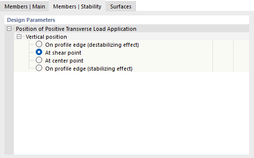
Load application point of positive transverse loads
If transverse loads (in the direction of the minor axis) exist, it is important to define where these forces act on the section. They can significantly influence the ideal critical moment: A load acting on the top flange of a bending beam in the direction of the shear center has a destabilizing effect. If the load acts on the bottom flange, it has a stabilizing effect. Use the selection fields to define the 'Vertical position'.