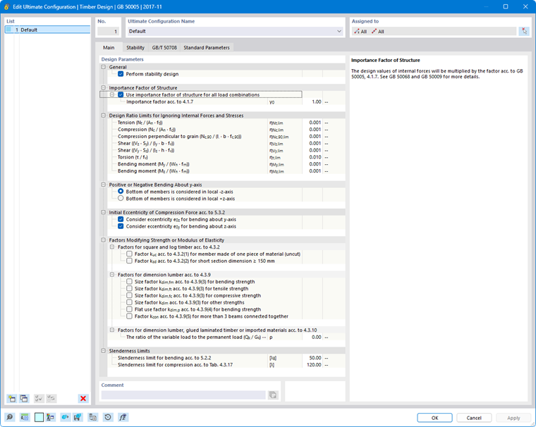
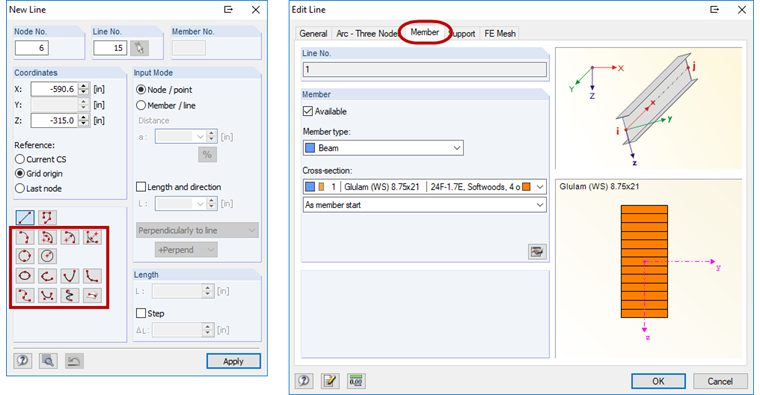
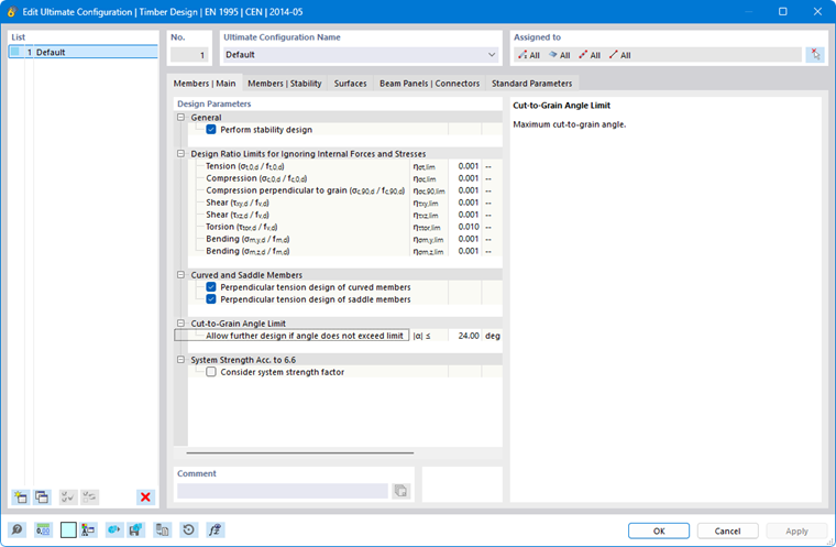
In the Members | Main tab of the “Ultimate Configuration” or “Strength Configuration” dialog box, you can configure basic settings for the design of members and member sets.
The “Design Parameters” are divided into several categories, which vary depending on the design standard. The following sections describe the parameters for these standards:
EN 1995
General
The “Perform stability design” check box controls whether stability analyses—such as those for flexural buckling or lateral-torsional buckling—are also performed in addition to cross-section checks. You should deactivate the check box if you do not wish to perform a stability analysis or if you have already considered the stability effects in the internal force calculation (for example, by performing a second-order analysis with imperfections and/or stiffness reduction).
If the stability analysis is activated, it is necessary to define and assign Effective Lengths to the respective members or member sets. Otherwise, a stability analysis is not possible. A corresponding message is displayed in the Errors & Warnings result table after the calculation. Tension members are excluded from this requirement, as they can only absorb tensile forces and do not require stability analysis.
Design Ratio Limits for Ignoring Internal Forces and Stresses
Design standards, which are typically based on manual calculations, contain design check formulas or interaction conditions that are often intended only for specific combinations of internal forces. However, when performing structural analysis on a 3D model, the internal forces obtained are generally very small. Although these values are irrelevant to the load capacity from an engineering point of view, strict adherence to the design standard can prevent certain design checks from being performed or force the use of less favorable interaction formulas. The design ratio limits therefore provide a simple and transparent way to neglect stresses resulting from very small internal forces in the design checks and to circumvent the problems mentioned above.
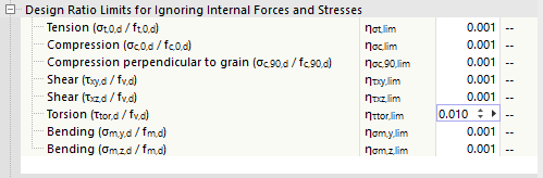
The limit value η describes the ratio of the actual stress to the design value of the strength, which is determined in a simplified manner based on the cross-section properties. The limit ratios of the design resistances are derived from the standard specifications and preset to very small values to allow for simplified design. You should therefore only use high limit values for testing purposes.
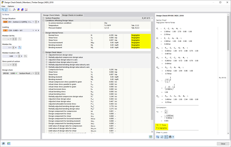
If an internal force falls below the limit value condition, the design is performed without a warning that the internal force is being neglected. However, in the Design Check Details, you can use the “Negligible” note next to the design internal forces to check which internal forces were neglected due to the limit values and were not considered in the design. If all internal forces at a given location are negligible, only the check of the negligible internal forces is specified as design.
Curved and Saddle Members
Use the check boxes to specify whether the design of compression perpendicular to the grain should also be performed for non-uniform cross-section distributions. This perpendicular tension design often proves to be a weak point in curved members.
“Saddle members” represent members with a section distribution of the “saddle” type. For these members as well, you can specify whether the perpendicular tension design should be performed.
Cut-to-Grain Angle Limit
For members with a linear or tapered section distribution, the wood fibers are cut through at the chamfered edge. According to [1] 6.4.2, the influence of the cut-to-grain angle α on the stresses at the cut edge shall be taken into account. According to the German National Annex, this angle shall not be too large and shall not exceed 24°. You can adjust the default limit value, if necessary, to allow for further design.
System Strength Acc. to 6.6
If, in the case of similar structural components spaced at equal intervals (for example, ceiling beams all aligned side by side), the continuous load distribution system is capable of transferring loads from one member to adjacent members, the strength of the structural components may be increased by a factor of ksys according to [1] 6.6. In this case, select the check box.
Increasing Shear Crack Factor
This category is available for design according to the German National Annex. It addresses the influence of cracks on the verification of shear resistance for structural components subjected to bending. If you enable this option, the factor kcr for the shear design of softwood cross-sections located more than 1.5 m from the ends of the members is increased by 30%. It is assumed that the cracks at these locations are only of minor dimensions.
NDS
General
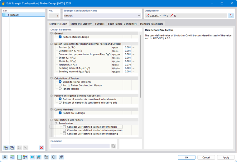
The “Perform stability design” check box controls whether stability analyses—such as those for flexural buckling or lateral-torsional buckling—are also performed in addition to cross-section checks. You should deselect this check box if you do not wish to perform a stability analysis or if you have already accounted for stability effects in the internal force calculation.
For further notes, see the General section in the description for the EN 1995 standard.
Design Ratio Limits for Ignoring Internal Forces and Stresses
The design equations in design standards are often intended only for specific combinations of internal forces. However, structural analysis using a 3D model typically also yields very small values for “secondary” internal forces, which—although insignificant for the load capacity from an engineering perspective—prevent certain design checks when the standard is strictly adhered to. The design ratio limits allow for the neglect of certain internal forces during design checks and thus circumvent the problems mentioned above. The limit value η describes the ratio of the actual stress to the design value of the strength.
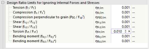
For further notes, see the Design Ratio Limits section in the description of the EN 1995 standard.
Calculation of Torsion
Use the check boxes to control how torsion is taken into account in the design checks:
- Check torsional limit only: It is allowable to carry out further design if the shear stress caused by torsion does not exceed the design strength value specified according to [2] Chapter 3.4. If it exceeds the limit value, no design is possible.
- Acc. to Timber Construction Manual: The torsional stresses are designed according to the specifications in [3] Chapter 4.6. In the section Design Ratio Limits, you can specify the limit ratio η at which torsional stresses generally become relevant for design.
- Ignore torsion: Although shear stresses resulting from torsion are checked during the design, they do not influence the design. If the design strength value is exceeded, the program only displays an informational note.
Positive or Negative Bending About y-Axis
According to [2] Table 5A and Table 5C, specific design values apply to glued-laminated timber structural components subjected to bending about the y/x-axis for positive bending (bottom side of the structural component under tension) and negative bending (top side of the structural component under tension). Specify whether the bottom side of the members being designed is in the positive direction of the local z/y-axis or in the reverse direction.
Curved Members
Curved glued-laminated beams are subjected to radial stresses, which it is necessary to take into account according to [2] Equation 5.4-1. The “Radial stress design” is therefore activated by default. For more information, see the technical article Design of Curved Glulam Beams According to ANSI/AWC NDS.
User-Defined Size Factors
The size factor CF is specified in [2], Section 4.3.6 for sawn timber and in Section 6.3.7 for round timber posts. By selecting the check box, you can manually specify the factor in each case.
User-Defined Flat Use Factors
The flat use factor Cfu is specified in [2] Section 4.3.7 for sawn timber and in Section 5.3.7 for glued-laminated timber. You can adjust this factor as needed.
User-Defined Stability Factor for Built-Up Columns
If a different factor Kf than that specified in [2], Section 15.3.2.4 is to be used when determining the stability coefficient for composite columns, you can specify it here.
User-Defined Size Factor
You can manually specify the size factor Cv for glued-laminated timber if it is not to be determined according to [2], Section 5.3.6.
CSA O86
General
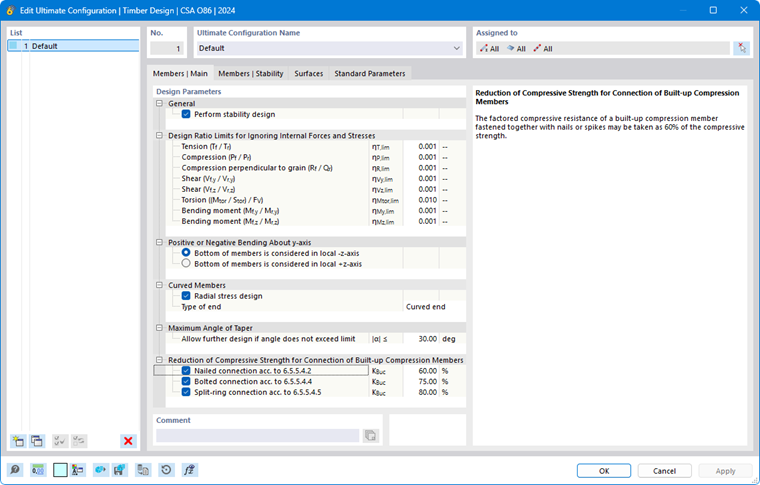
The “Perform stability design” check box controls whether stability analyses—such as those for flexural buckling or lateral-torsional buckling—are also performed in addition to cross-section checks. You should deactivate this check box if you do not wish to perform a stability analysis or if you have already accounted for stability effects in the internal force calculation.
For further notes, see the General section in the description for the EN 1995 standard.
Design Ratio Limits for Ignoring Internal Forces and Stresses
The design equations in design standards are often intended only for specific combinations of internal forces. However, structural analysis using a 3D model typically also yields very small values for “secondary” internal forces, which, although insignificant for the load capacity from an engineering perspective, prevent certain design checks when the standard is strictly followed. The design ratio limits allow for the neglect of certain internal forces during design and thus circumvent the problems mentioned above. The limit value η describes the ratio of the actual internal force to the design value of the cross-section resistance.
For further notes, see the Design Ratio Limits section in the description of the EN 1995 standard.
Positive or Negative Bending About y-Axis
According to [2], Table 5A and Table 5C, specific design values apply to glued-laminated timber structural components subjected to bending about the y/x-axis for positive bending (bottom side of the structural component under tension) and negative bending (top side of the structural component under tension). Specify whether the bottom side of the members being designed is in the positive direction of the local z/y-axis or in the reverse direction.
Curved Members
Curved glued-laminated timber beams are subjected to radial stresses, which it is necessary to take into account according to [4], Section 7.5.6.7. The “Radial stress design” is therefore activated by default.
Select the “Type of end” of the beam from the list:
- Curved end
- Tangential end
The end type determines the minimum curvature radius to be applied according to [4], Table A.7, based on the lamella thickness for glued-laminated timber specified in the Standard Parameters tab.
Maximum Angle of Taper
Specify the limit value for the angle α for tapered glued-laminated timber members. If the angle exceeds this limit value, the beam will not be designed.
After the calculation, you can check the precamber angle and the limit value in the Design Check Details.
Reduction of Compressive Strength for Connections of Built-Up Compression Members
The compressive strength of composite structural components is limited to a specific percentage of the component’s compressive strength according to [4], Section 6.5.5.4, the compressive strength of composite members is subject to a specific limitation of 60% of the member’s compressive strength. Depending on the fastener type, the strengths shall be reduced as follows:
- Nail connections: 60%
- Bolted connections: 75%
- Split-ring connections: 80%
You can adjust the factored compressive strengths as needed.