


For some standards, the Surfaces tab is available in the “Ultimate Configuration” or “Strength Configuration” dialog box. Here, you can configure basic settings for the design of surfaces made of mass timber, glued-laminated timber, or wood-based materials.
The “Design Parameters” are divided into several categories, which vary depending on the design standard. The following sections describe the parameters for these standards:
EN 1995
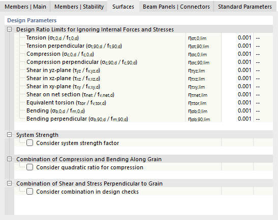
Design Ratio Limits for Ignoring Internal Forces and Stresses
This category manages user-defined limits that apply to very small stresses: If the ratio η of the actual stress to the design strength value is less than the limit value, the stress is not taken into account during the design. The background for this option is described in more detail in the chapter Members | Main.
System Strength
If the continuous load distribution system in similar structural components with equal spacing (for example, floor beams all aligned side by side) is capable of transferring loads from one surface to adjacent surfaces, the strength of the structural components may be increased by a factor of ksys according to [1] 6.6. In this case, select the check box.
Combination of Compression and Bending Along Grain
If no stability analysis is performed, the compression component may be considered quadratically for combined bending and compression actions according to [1], 6.2.4(1). This option can be activated for mass timber, but not for cross-laminated timber.
Combination of Shear and Stress Perpendicular to Grain
If the interaction between shear in the xy-plane and tension or stress perpendicular to the grain is to be considered in the design checks, select the check box.
NDS
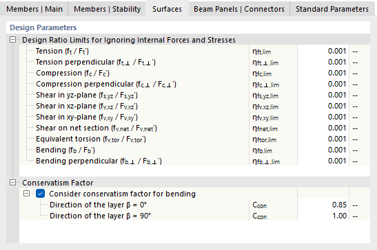
Design Ratio Limits for Ignoring Internal Forces and Stresses
This category manages user-defined limits that apply to very small stresses: If the ratio η of the actual stress to the design strength value is less than the limit value, the stress is not taken into account in the design. The background for this option is described in more detail in the chapter Members | Main.
Conservatism Factor
For design of cross-laminated timber (CLT) panels, ANSI/APA PRG 320 requires to multiply the calculated moment resistances in the direction of maximum strength (β = 0°) by a factor of 0.85 for conservative reasons. This factor for out-of-plane bending is referred to in the program as the “Conservatism Factor” Ccon and is activated by default. You can check the factors for the directions of the layers and adjust them, if necessary.
CSA
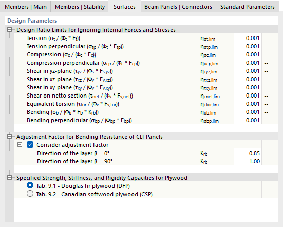
Design Ratio Limits for Ignoring Internal Forces and Stresses
This category manages user-defined limits that apply to very small internal forces: If the ratio η of the actual stress to the design value of the cross-section resistance is less than the limit value, the stress is not taken into account in the design. The background for this option is described in more detail in the chapter Members | Main.
Adjustment Factor for Bending Resistance of CLT Panels
For design of cross-laminated timber panels, [3], Section 8.1.4.3.1 requires to multiply the calculated moment resistances in the direction of maximum strength (β = 0°) by a factor of 0.85 for conservative reasons. This adjustment factor for out-of-plane bending is activated by default. You can check the adjustment factors Krb for the directions of the layers and adjust them if necessary.
Specified Strength and Stiffness Capacities for Plywood
Different strength capacities apply to plywood panels depending on the material. Select the relevant option from the list: