In the Deflection tab of the "Edit Surface" dialog box, you can make the settings for the deflection analysis of a surface.

Deflection Analysis
Use the “Surface type” to specify which deflection limit values are to be used for the design. They are specified in the Serviceability Configurations dialog box for various design situations of surfaces with support on both sides or on one side.
The “Displacement reference” controls which reference model is used for the design of deformations. The list contains three options:
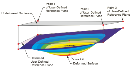
- Deformed user-defined reference plane: If the supports have very different displacements, you should specify an inclined reference plane for the displacement uz to be designed. Define the plane in the “User-defined reference plane” section by three points of the undeformed structural system. RFEM determines the deformation of the three definition points, defines the reference plane through these shifted points and uses the related maximum deformation uz for the design.
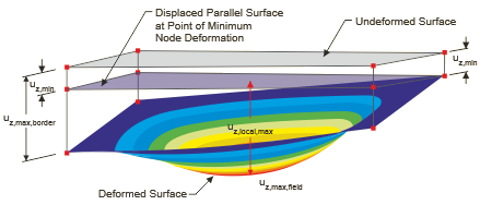
- Parallel surface at the point of minimum nodal deformation: This option is recommended if the support of the surface is yielding. The maximum deformation uz is related to a reference plane shifted parallel to the undeformed structural system, which RFEM places using the node with the smallest displacement value uz,min.
- Undeformed structural system: The local deformations uz are taken directly from the results and used for the design.
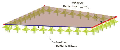
The limit value of the deflection depends on the “Reference length” Lz. With the definition type options “By maximum boundary line” and “By minimum boundary line” (default setting), RFEM determines the length of the longest or shortest edge from the surface geometry and sets the reference length automatically. If you want to define the reference length, select the “Manually” definition type in the list and then enter the value.