


The result tables in the Design Ratios on Surfaces category contain the results data for the performed design checks, along with the respective design ratios.
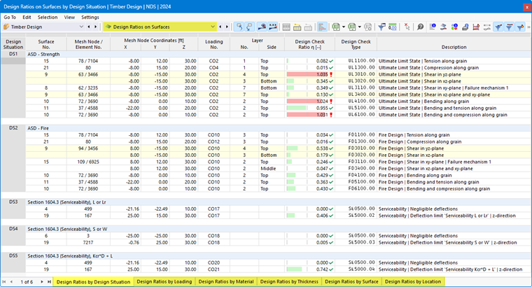
The surface results are sorted in the tabs according to the following criteria:
- Loads (design situations, load combinations)
- Surface properties (materials, thicknesses)
- Objects (surfaces, FE mesh points)
Surface No.
For each design criterion, the number of the surface with the highest design ratio is specified.
Mesh Node / Element No.
The number of the FE mesh node for which the maximum design ratio was determined is specified in each case. A second number identifies the finite element adjacent to the FE node if there are differing design-relevant internal forces at that location.
Mesh Node Coordinates
The three columns display the global coordinates X, Y, and Z of the FE mesh nodes.
Design Situation
This column lists the numbers of the design situations for which the individual design ratios are available.
Loading
The numbers of the load or result combinations that are governing for the respective design checks are specified.
Layer Side
The stresses are analyzed for the following locations on the surface cross-section:
- Top
- Middle
- Bottom
You can show or hide the face axes using the Local Axis Systems of Surfaces on/off option in the face shortcut menu. Another way is to use the Navigator – Display (Model → Basic Objects → Surfaces → Face Axis Systems x, y, z).
Design Check Ratio
This column lists the design conditions according to Standard. The degree of each design ratio is indicated by the length of the colored bar.
Design Check Type
Each design is identified by a numerical code. For example, the ultimate limit state design checks according to Eurocode are identified by the code “UL”, while the serviceability limit state design checks are identified by the code “SE”. The type of design is explained in the Description column.
Design Check Formula
You can activate this column in the Result Table Manager. It lists the equations from the standard used to perform the design checks.
Description
Each design check is explained with a brief description referencing the relevant chapter in the standard.
You can display the design check details for a specific design ratio by clicking the
 button or double-clicking the row.
Filtering Results
The chapter Design Ratios on Members describes how to filter the results by limit state and by design ratio.