


There are two ways to modify an inserted plate. One is the Plate Cut component, the other the Plate Editor. The latter allows you to adjust the plate corners by chamfering, notching, rounding, or drilling a round hole through the plate.
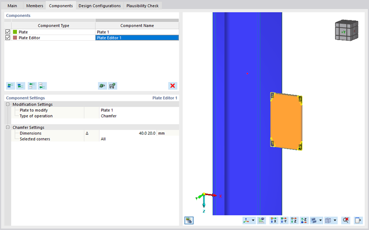
Modification Settings
First, it is necessary to specify the plate to be edited. Only the inserted plates are in the combo box; member plates cannot be modified by this component.
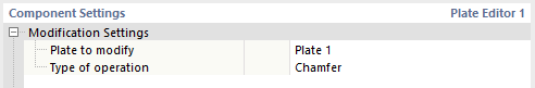
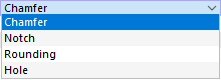
The second row of the "Modification Settings" category is the type of operation. You can select from four types of modification: Chamfer, Notch, Rounding, and Hole.
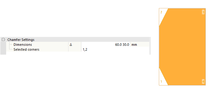
For the definition of a chamfer, notch, or rounding, you have to select the location of the modification. For this purpose, you can edit the Selected corners row in the next category where the default value is All. If only some of the corners need to be modified, enter their numbers according to the numbering in the graphics in this row. The format of the numbers can be the list of corners, interval, or a combination of both.
All the modifications made by this component are executed on the original shape and size of the plate. This condition is selected to prevent the subsequent changes (for example, a plate cut) to invalidate this component.
Chamfer Settings
The additional settings when applying a Chamfer modification consist of two parameters. The first parameter is the dimension of the chamfering. It is composed of two values that define the length along both perpendicular plate edges of the relevant plate corner. In the second row, you can enter the corners to be chamfered.
Notch Settings
The second type of operation is the Notch. When defining the detailed setting, enter two values to specify the dimensions along the plate edges.
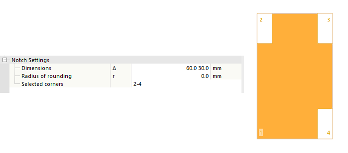
The cut is made perpendicularly to the plate edge in both directions. The intersection point does not have to form a 90-degree angle; therefore, the parameter on the following row defines the radius between both cuts and forms a rounding. If no rounding is required, the zero value may remain. In the last row, you can specify the relevant corners on which the notching is to be made.
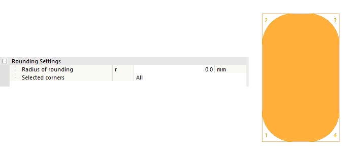
Rounding Settings
Another type of plate corner modification is Rounding. Using this modification, each of the selected corners is rounded with the radius specified in the first row of the detailed settings. The rounding is carried out on all plate corners selected in the row below the radius.
Hole Settings
The last type of modification is the Hole. Unlike the previous ones, this modification is not specific to corners. There are four basic geometric shapes you can select from:
Circle: A circular opening is defined by its center coordinates and diameter.
Rectangle: A rectangular opening is defined by its center coordinates, its side length, and a rotation in the plate plane.
Polygon: The contour corresponds to a circle that is approximated by a polygon. In addition to the center and diameter, the number of straight line segments of equal length in the polygon is defined. A rotation angle other than 0.0° causes the contour to rotate in the plate plane.
Hexagon: The hexagonal opening is characterized by the center coordinates, the height, the side length of one edge, and the width at the widest point. The remaining edge lengths are set automatically. This contour can also be rotated in the plate plane.
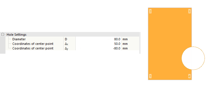
The center of the hole does not have to be in the plate; the hole can also be placed at the edge of the plate. However, the cutting contour have to reach the plate edge, so that at least part of the plate is cut off by this modification.