


The component Base Plate allows you to design base plate connections with cast-in anchors. The plate, welds, anchorage, and steel-concrete interaction are analyzed.

Objects to Connect
In the first category of the component settings, you specify which member has a base plate.
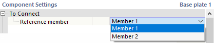
The list shows all members connected to the node. Select the 'reference member' (the column). A nodal support does not necessarily have to be assigned to the node.
Position
This category allows you to place the base plate at a distance from the member end and to rotate it.
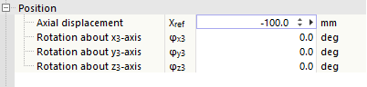
The 'longitudinal offset' describes the (vertical) distance from the node. If you want to apply a 'rotation' to the base plate, enter the corresponding angles around the local axes. You can show the coordinate system using the
![]() button at the bottom of the graphic area.
button at the bottom of the graphic area.
Plate
The plate of the base plate component creates the connection between the reference member and the concrete block.
Select the appropriate material from the defined materials, or create a new material using the
![]() button. Then, enter the thickness of the plate.
button. Then, enter the thickness of the plate.
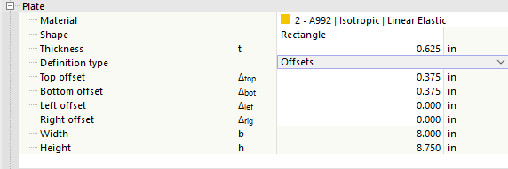
You can define the plate geometry via 'offsets' or 'dimensions and position'. Select the corresponding option in the list.
Offsets
The plate size results from the cross-section dimensions of the reference member. Using the 'offset' in the four directions, you can define how far the plate protrudes beyond the boundary frame of the cross-section. The resulting width and height are given in the last lines; these values cannot be changed.
Dimensions and Position
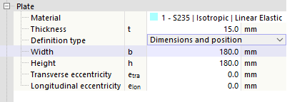
You can directly specify the size of the plate. The position is related to the cross-section of the reference member. If the slab is not to be arranged centrically, you can define a 'transverse eccentricity' and a 'longitudinal eccentricity' related to the connection node and shift the plate.
Concrete Block
The concrete block forms the "foundation" of the base plate component.
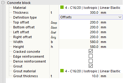
Select the appropriate material from the defined materials, or create a new concrete material using the
![]() button. Then, enter the thickness of the concrete block.
button. Then, enter the thickness of the concrete block.
You can define the geometry via 'offsets' or 'dimensions and position'. Select the corresponding option in the list. Both options correspond to those for defining the plate geometry (see Offsets).
The 'cracked concrete', 'edge reinforcement', and 'dense reinforcement' check boxes affect the effective area Aeff of the base plate under compression: If the concrete cracks, this area becomes slightly smaller; if edge reinforcement and dense reinforcement are present, the effective area becomes slightly larger.
If a blinding layer is provided between the steel plate and the concrete block, select the 'mortar' check box. Then, define the 'mortar material' and specify the 'mortar thickness'.
Shear Transfer
This category controls how shear forces are transferred between the reference member and the concrete block.
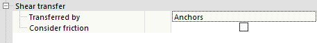
Define whether the shear transfer should occur via the anchors or a shear lug. If you also want to 'consider friction', select the corresponding check box. The friction coefficient is stored in the Ultimate Configurations in the 'Concrete Block' category.
Shear Lug
If shear transfer via shear lugs is selected, its properties are specified in this section.
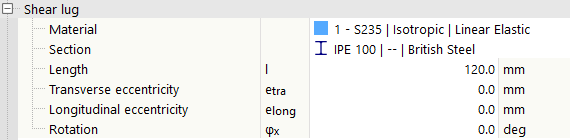
Assign a material and a cross-section to the shear lug. Furthermore, the length must be defined.
The position of the shear lug is always related to the center of the base plate (plate). It is defined by the transverse or longitudinal eccentricity (in the plane of the plate) and the rotation of the shear lug (about its longitudinal axis).
Anchors
The anchors absorb the tensile forces (and possibly also the Shear Forces). In this category, you can define the properties of the bolts.
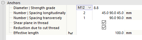
Select the 'diameter' and the 'strength class' of the anchor bolts in the lists.
Then, specify the 'number' as well as the 'longitudinal distance' and 'transverse distance' of the anchors. The distances of a subgroup can also be entered as a multiplication (e.g., 3*50). Missing entries are automatically completed consistently with the geometry of the end plate. The
![]() button in the graphic area is also helpful here to switch to the symbolic representation of the parameters.
button in the graphic area is also helpful here to switch to the symbolic representation of the parameters.
With the 'thread in shear plane' and 'reduction due to cut thread' check boxes, you can control whether the strengths should be reduced accordingly.
The value hef represents the effective anchorage depth of the anchors in the concrete block. The length of the anchors thus results from the thickness of the base plate and, if applicable, the mortar layer, the anchorage depth, and the required length for the nut and washer.
Anchor Types
Three anchor types are available: Post-installed | Bonded, Cast-in | Headed studs, and Cast-in | Hooked anchors. For post-installed anchors, only the embedment depth needs to be specified. The anchor heads are defined by the thickness of the head, a diameter specification for round heads, and an edge length for square heads. For hooked anchors, the hook length must be defined. The permissible range depends on the hook length and the applied design standard. Furthermore, the factor for characterizing the composite conditions, which is included in the concrete interaction checks, is specified.

Welds
The last category controls which welds connect the edges of the reference member (column) to the plate of the base plate. If you deactivate one of the check boxes, no weld is arranged on the corresponding cross-section part.
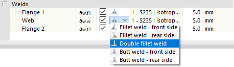
When you click in the column to the right of the check box, you can call up a list of weld types. Various types of fillet and butt welds are available for selection. For fillet welds, you must specify the thickness of the weld.
