Some of the components such as End Plate, Fin Plate, Cleat, End Plate to Plate, Connecting Plate and Plate to Plate have the definition of fasteners (bolts) included. However, you can also use the Fasteners as a separate component when you want to connect two or more general plates. This component connects one or more plates (or member plates) to other plates or member plates that are already present in the model.
To Connect
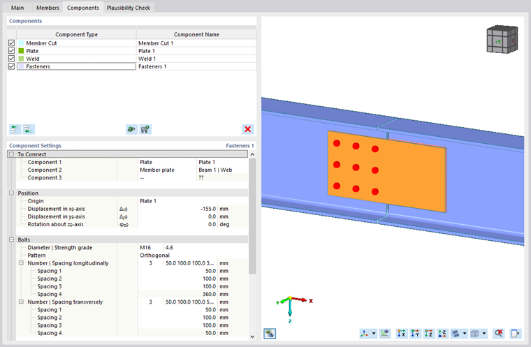
In the first category of the "Component Settings", define the components that are to be connected. These can be plates or member plates. You have to select at least two components, and you can connect up to ten components.
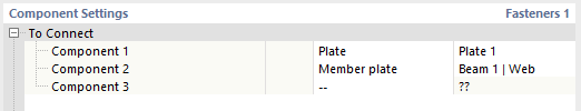
Component 1 is the governing plate. This means that bolt heads are placed on it, and by default the origin for fasteners (bolts) is set at the same position. Component 2 is a reference component; fasteners (bolts) are oriented in the direction set by that component. All following components are automatically lined up in that direction if they are parallel to Component 1; if not, they are set as nonvalid and moved to the last position in the list of components.
Position
The second category controls the positioning of the fasteners group.
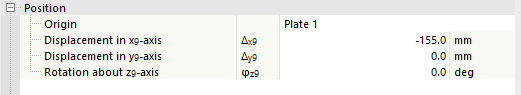
Select the "Origin" component to which the displacements and rotation will be related. The default value is the plate or member plate selected as Component 1, but you can choose any component defined in the To Connect category as reference. Based on the coordinate system of the reference component, you can move or rotate the origin of the fasteners in the plane defined by the origin component to fit your needs.
Bolts
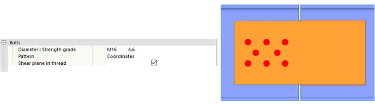
This category manages the properties of the Bolts.
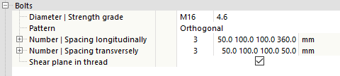
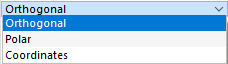
The first row contains the required bolt diameter, followed by the bolt class. In the second row, you can choose the pattern of the bolt group. The possibilities are Orthogonal, Polar, and Coordinates.
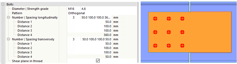
For the Orthogonal option, you can define the number of rows and spacing of bolts horizontally and vertically. When you expand the Number ǀ Spacing longitudinally or Number ǀ Spacing transversely items, you can define each space in a separate row. The spacing values for a subgroup can also be entered as a multiplication (e.g., 3*50). Missing entries are automatically filled in to be consistent with the geometry of the plates.
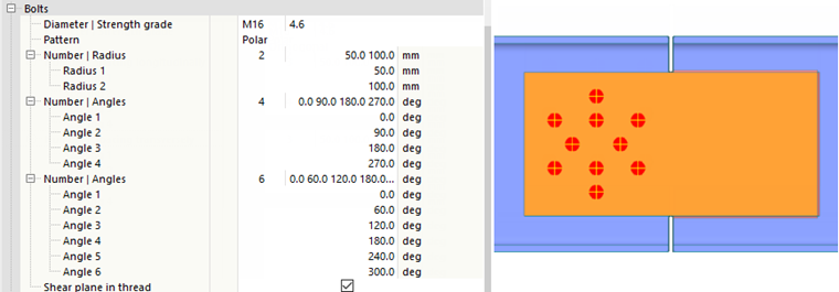
For the Polar option, you can define the number of circles where bolts can be placed, and their radius. Then you define the number of bolts in each circle and the angle for each bolt. When you open any Number ǀ Angles item, you can define each angle in a separate row.
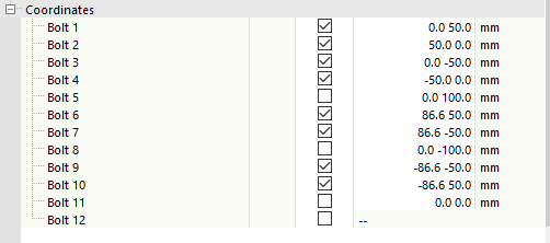
For the Coordinates option, you can define specific coordinates for each bolt separately in the Coordinates category. After changing to the Coordinates pattern, the bolts remain at the position defined before switching.
Coordinates
In the final Coordinates category, you will find a list of defined bolts, checkboxes, and coordinates for each bolt . You can deactivate or activate a specific bolt by means of its checkbox. When you have set the Coordinates pattern in the Bolts category, you can also modify the coordinates of a specific bolt. For all other patterns, the coordinates of each bolt are read-only.
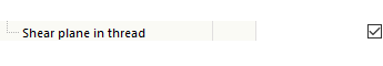
Shear plane in thread
When the "Shear plane in thread" option is activated, the lower strength (reduced area) according to the selected design standard is considered for the bolt shear check.