


In the Ultimate Configurations dialog box, you can define the basic specifications for the ultimate limit state design. You can create several configurations and assign them to joints accordingly. The specifications are applied to a submodel that is created in the background for the calculation.

A "list" on the left shows all configurations available in the model. You can use the
![]() button to create a new configuration, based on the default values of the
Base Data
of the specified design standard. As an alternative, you can copy the existing configuration by using the
button to create a new configuration, based on the default values of the
Base Data
of the specified design standard. As an alternative, you can copy the existing configuration by using the
![]() button and then adjust the design parameters. The
button and then adjust the design parameters. The
![]() button deletes the configuration selected in the list.
button deletes the configuration selected in the list.
Main
The Main tab manages important "Design Parameters" that affect the design checks of the stress-strain analysis.
General
The "Perform buckling analysis" check box controls whether ultimate limit state design checks are carried out in addition to the buckling analyses. This option is deactivated by default. Select the check box if you want to perform a buckling analysis. You can then check the buckling analysis parameters in the Buckling tab.
The “Preliminary design” check box activates the automatic reduction of the considered load combinations. The probable governing load combinations are filtered out and designed based on the extreme section loads in the connected members.
Partial Safety Factors
The material partial safety factors γM as well as γC, and γinst affect the design. In this category, you can check the preset values and adjust them, if necessary.
Analysis
The Analysis Type list provides a selection option among the following methods of analysis:
- Geometrically linear analysis
- Second-order (PΔ) analysis
- Large deformation analysis
If the calculation does not converge in the case of the default setting of the maximum of 100 iterations, you should increase the "Maximum number of iterations" accordingly. Further information can be found in the chapter Static Analysis Settings of the RFEM manual.
For better convergence and to avoid instabilities in nonlinear structural systems, it is recommended to use several load steps. However, a large "Number of load increments" has a detrimental effect on the speed of the calculation.
Design
If necessary, you can adjust the value of the "Limit plastic strain". Based on EN 1993‑1‑5, Annex C, the default value is 5%. The parameters "Slip factor for preloaded bolts" and "Preloading force factor" affect the design when using high-strength bolt connections. Optionally, you can "perform elastic verification of free bolt shank".
In principle, a plastic reserve of the bolt shafts is assumed. This is not taken into account by activating the “linear axial behavior of bolts.” The factors e and p are used as a basis for determining the allowable edge and axial distances of bolts. The specified standard values are based on the respective standards.
Concrete Block
In this category, you can specify which "Friction coefficient" should be applied for the shear transfer of the Base plate component. It affects the friction between the base plate and the grout. The value of 0.20 is preset, which is recommended for cf,d in EN 1993‑1‑8, 6.2.2.
The "Lower limit of contact stress for effective area in compression" is preset with the value of 5‰. This ensures that only areas with significant compressive stresses are included in the determination of the effective area. Areas with very small compressive stresses are neglected.
In the case of the "Method for effective area of base plate in compression", you can select between two options in the list:
- EN 1993-1-8
- FEM analysis
Modeling
A "member length factor" specifies the length of the member equivalent model. The larger value of the length and width of the circumscribed rectangle is multiplied by the value entered here. Furthermore, you can influence the "number of segments" that are created for circular geometry. Optionally, you can arrange "welds on full length of member plate edge" and control whether segmented (for example curved) welds should be designed continuously or not.
Mesh
The last category provides various setting options for an FE mesh, as different meshes may be required depending on the joint type. You can specify the minimum and maximum element size in "General".
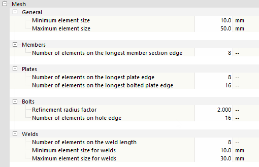
Furthermore, you can adjust the number or size of the finite elements for various components, such as members, plates, bolts, or welds, to correspond to the joint geometry. The greater the number of elements or the smaller their size, the finer the meshing.
The default settings of the design parameters should be used for the most cases, as they provide sufficiently accurate results with regard to the calculation time.
Plate Buckling
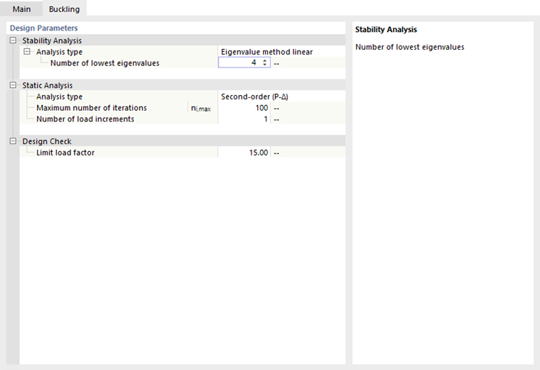
The Buckling tab is displayed when selecting the Perform buckling analysis check box in the "Main" tab.
Stability Analysis Software
In this category, you can define an "analysis type" and a number of "eigenvalues" for the buckling analysis.
There are three eigenvalue methods available in the list.
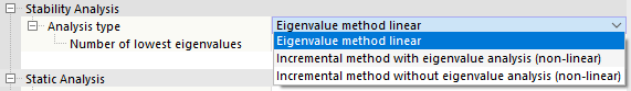
- With the default setting "Eigenvalue method linear", the mode shapes are determined linearly. The properties of the nonlinearly acting elements, such as tension members or supports with failure criteria, are not taken into account.
- The "Incremental method with eigenvalue analysis (non-linear)" option allows you to consider all nonlinearities when determining mode shapes. In the course of the gradual load increasing until failure occurs, the failure criteria and nonlinear effects of members, supports, or hinges are determined. The calculation is performed iteratively, and thus requires a corresponding amount of time. With this method, you can reliably determine the lowest eigenvalue only.
- With the "Incremental method without eigenvalue analysis (non-linear)", the load is increased until failure occurs. No mode shapes are determined.
Four eigenmodes are preset as the "number of lowest eigenvalues". Thus, it is usually possible to obtain a reliable information about the buckling behavior.
Structural Analysis
The buckling analysis covers the same calculation parameters as described for the general settings in the Analysis section.
Design
The plate buckling design is considered to be fulfilled if the "limit load factor" is 15 or more. This value is recommended in EN 1993‑1‑1, 5.2.1(3) for αcr for plastic design. Therefore, a critical load factor of less than 15 represents a stability failure. You can change the default value, if necessary.