


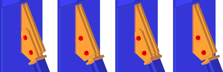
The component Connection plate is a complex component consisting of other components (i.e., cap plate, tongue plate, gusset plate, welds, and bolts). All these subcomponents can be configured within the Connection plate. However, the gusset plate can also be configured outside of this component.
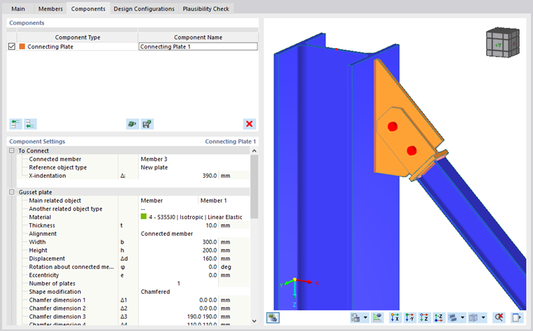
To connect
First, you have to define the member that is connected by this component.
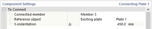
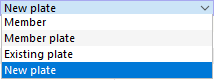
Then, you can select whether the reference object is an existing object (Member, Member plate or Existing plate) or a new gusset plate. For existing objects, a new combo box is displayed in the same line, where you can select the actual reference.
In the last line, the X-recess is defined, i.e., the distance of the end of the connected member from the theoretical member end (i.e., from the connection origin).
If you select New plate as the reference object, a new input category Gusset plate appears.
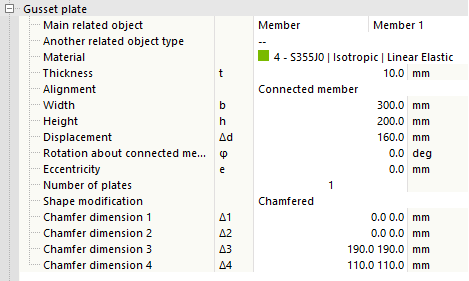
The Gusset plate is bounded by the main object selected in the first line. This object can be either a member or a plate (including member plates). In the next line, you can define another associated object, which is optional if you insert the gusset plate between two existing objects. After selecting the material and plate thickness, you can select to which plane the gusset plate should be aligned. The Connected member option aligns the gusset plate to the XZ plane of the connected member; the Main reference object option aligns the plate to the plane formed by the longitudinal axes of the main reference object and the connected member.
Further parameters define the plate dimensions, displacement along the longitudinal axis of the main reference object, rotation about the longitudinal axis of the connected member, and eccentricity of the plate out of the plane. The required number of plates can be set to 1 or 2.
The gusset plate can be modified by offset, chamfers, or a combination of both. For each of the modifications, a new definition line appears. The offset value is measured from the end of the connected member (including end modification) toward the gusset plate and defines the boundary for cutting the plate. Chamfers can be set for all corners separately; for better orientation, you can see the numbering of the corners when editing the values. The combination of modifications means that the offset and the chamfers are applied jointly.
Tongue plate
The tongue plate connects the Cap plate (defined further below) to the reference object. It is basically an extension of the connected member in the form of a plate. If the reference object is an existing object, the position of the tongue plate is adjusted to it. If the reference object is a new plate, on the other hand, the tongue plate is placed centered to the connected member and the position of the new gusset plate is adjusted to the tongue plate.
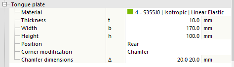
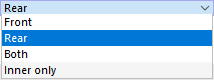
The definition consists of the material and the dimensions of the plate, followed by the position. The position can be selected as 'Front, Back, or Both. The fourth option Only interior creates only one tongue plate between the two in the case of two gusset plates.
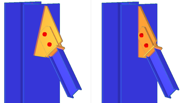
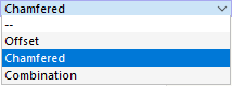
Remote corners of the tongue plate can be modified by chamfers or rounding. In that case, a definition line appears for this modification. Both remote corners have the same corner modifications.

Cap plate
The Cap plate serves as a connection between the connected member and the Tongue plate. The connected member is welded from one side of the Cap plate, the Tongue plate from the other side.
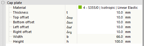
The definition of the cap plate consists of the selection of the material, followed by the plate thickness and the offsets from the edges of the connected member. The overall dimensions of the plate can be checked at the bottom of the input node.
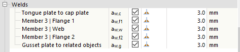
Welds
As already mentioned, this component creates many new components in the connection and all these components need to be connected together. The welds are placed between the connected member and the cap plate, between the cap plate and the tongue plate, and between the gusset plate and the reference object. If the gusset plate is created outside of this component, the weld is not calculated here. In general, for each contact of two plates within the above-mentioned connections, a new definition line is used. The definition includes a check box indicating whether the weld should be used, the combo box for the weld type, and (for the Fillet weld option) the weld thickness.
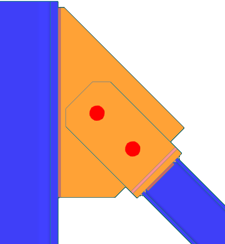
Bolts
The last input node is for the definition of the Bolts that connect the Tongue plate and the Gusset plate. Detailed information on bolt definition can be found here
