There are several methods to modify objects used in a joint. One of them is the Member Cut component. It allows you to modify the member end in the joint area as a whole. There are four types of cutting, based on the reference object for the cut: cutting by member, by plate, by auxiliary plane, and by auxiliary plane.
To Cut
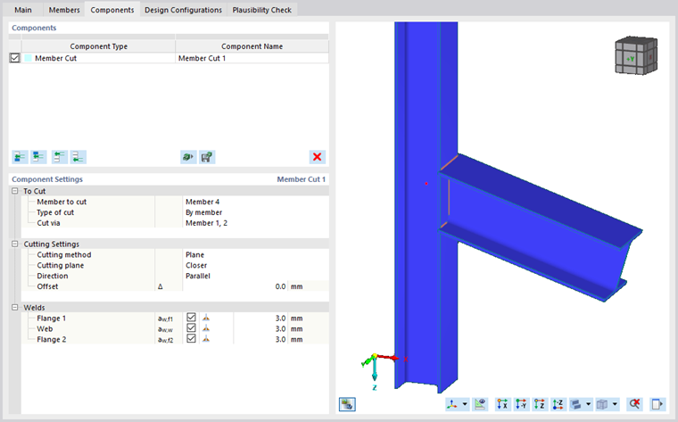
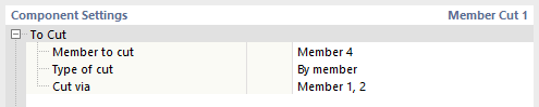
In the first category of the "Component Settings" area, you can define the structural component to be cut followed by the type of cut. As mentioned above, there are the types “By member,” “By plate,” “By auxiliary plane,” and “By auxiliary plane”. Since the Cutting Settings depend on the selected type of cut, the detailed description of the individual cut type is provided below. The last row determines the reference object that is governing for the cut.
Cutting Settings
The input details of this category depend on the selected type of cut.
By Member
The cut type by member is used when a member (Cut via) determines the space of another member (Member to cut) that needs to be modified due to potential collision.
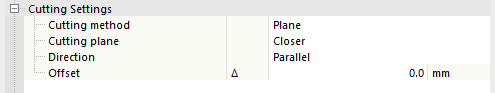
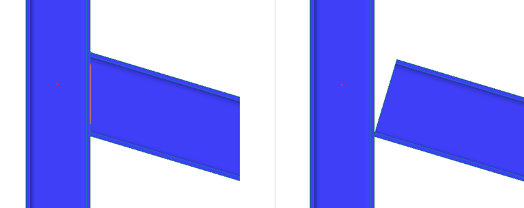
The first line in the "Cut Settings" category controls the Cutting method. The first of the available methods is the Plane option which guides the cut by the closest plane of the bounding box of the reference element. The second method is the Surface option. It only cuts the intersection of the cross-sections.
_Plane_(left),_Surface_(right).png?mw=760&hash=27e152b827b62742cdc5fcff5a4378659ef3f3a2)
The Bounding box and Convex hull options are particularly suitable when creating intersections for asymmetrical cross-sections.
The cutting method is symbolized by bitmaps in the graphic area of the dialog box that you can activate using the
![]() button.
button.
When cutting by plane, you can select which Cutting plane is the controlling one, that means, whether it is Closer or Farther from the connected member side. The default status is Closer, as it is the more common case. Below, you can see some examples of both cutting options. The first image shows structural components with no cut applied. In the middle image, the beam is cut via the column with the Cutting plane option set to Closer. In the last image, a new member cut was added, with the column being cut via the beam and the Cutting plane option set to Farther.
,_Closer_(middle),_Farther_(right).png?mw=760&hash=f2437a33cede294697038a70877b74ec624317ac)
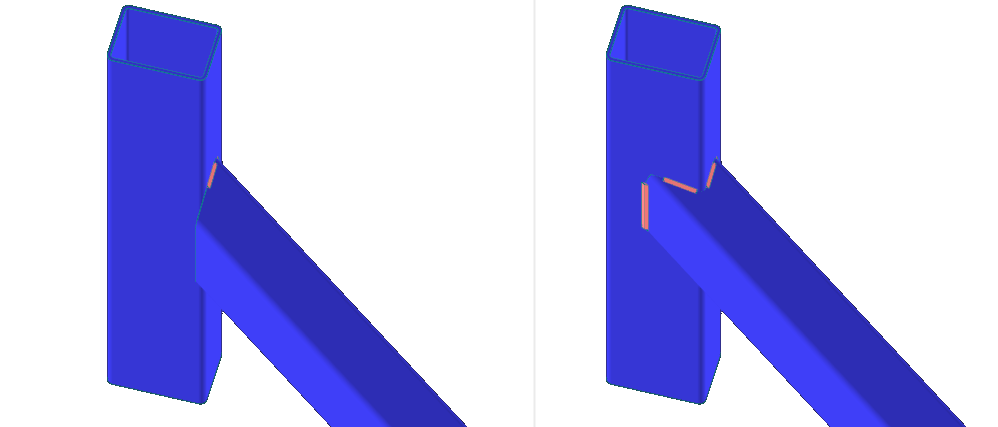
The last setting that applies specifically to cutting by plane, is the Direction of the cut. There are two options: Parallel or Perpendicular. Parallel means that the plane of the cut is parallel to the reference member (Cut via). The Perpendicular direction means that the cutting plane is perpendicular to the connected member axis at the closest point of contact of both members.
For all cutting methods, it is also possible to set an Offset where the actual cut is made. For Plane and Surface, both positive and negative values are allowable.
By Auxiliary Plane
Instead of an existing structural component, you can use an auxiliary plane as a reference object. In this case, the additional settings consist of the Direction of the cut and the Offset, similarly to the cut by member. The options for the Direction are the same: Parallel to the auxiliary plane or Perpendicular to the connected member axis at the closest point of contact with the auxiliary plane.
_Parallel_(left),_Perpendicular_(right).png?mw=760&hash=8f8bf2e8d1dfe914557ff1d39cbda38c9a4643b2)
By Plate
The By plate type of cut is similar to cutting by auxiliary plane. The main difference is that the auxiliary plane has no thickness, whereas the plate does. Therefore, it is possible to select the cutting method either by Plane or by Surface. In addition to the cutting method, there are the additional settings Direction and Offset, as described above.
__Parallel_(left),_Perpendicular_(right).png?mw=760&hash=9d7f268cb7b9d2a4872c1b4cf3f1876e0595720b)
By Auxiliary Plane
The By auxiliary plane type of cut allows for a three-dimensional member cut without a defined reference component. The intersection of the member to be cut with the auxiliary plane is removed by a offset that can be defined.
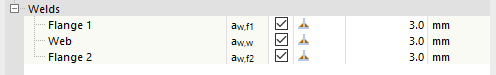
Welds
In cases where the cut results in a contact between plates or member plates, it is possible to define a weld. For each contact between a plate edge and a plate face, a new weld definition line appears in the Welds category of the "Component Settings" area. The definition contains a check box that controls whether to use the weld, a Weld type text box, and, for the Fillet weld option, the option to define the weld thickness.