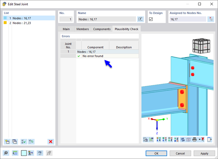
For each joint, a plausibility check is performed to detect inconsistencies in the modeling. This check is necessary to successfully complete the definition of a joint. The result of the check is displayed in this tab.
A distinction is made between warnings and error messages. Warnings are based on design guidelines from the design standards and indicate a violation of these guidelines in the joint design. They are marked with a yellow warning symbol and have no influence on creating the model or the calculation. Error messages indicate a serious error in the modeling that makes calculation impossible.
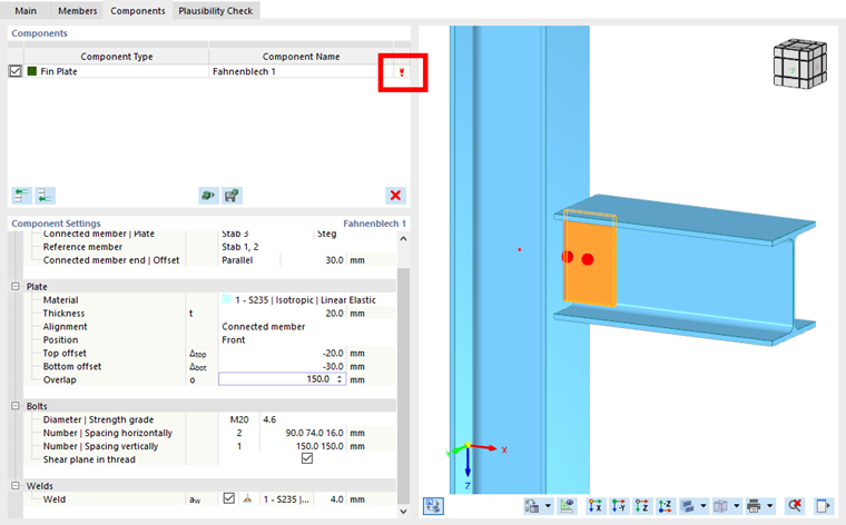
The add-on usually reports inconsistencies in the form of a red exclamation point when entering the data, thus indicating an error in the modeling. In the following example, there is a problem with the bolt spacing, possibly caused by a typo.
The incorrect entry is shows in detail in the "Plausibility Check" tab. The most common error messages are described below.
Weld extends beyond connected component.
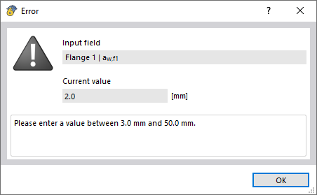
There is an error in the weld input. The components describe which weld seam and end plate are involved.
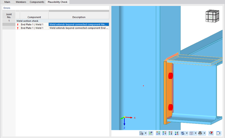
The problem can be solved by adjusting the input data in the "Main" tab. In this case, the thickness of the weld seam is changed to ensure error-free modeling. Make sure that the value of the weld is in the range between 3 and 50 mm.
Invalid weld.
If the message "Invalid weld between X and Y" appears, it is necessary to recheck those components that are named by the plausibility check.
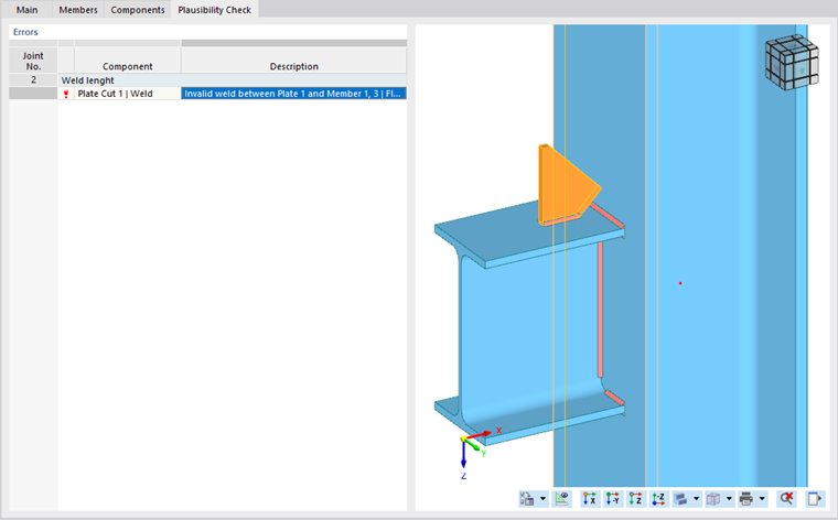
In our example, a weld seam has been specified that cannot be executed. Deactivating the weld allows for an error-free plausibility check.
Unassigned ultimate configuration.
This message appears if the joint has no ultimate configuration assigned. To fix this error, switch back to the "Main" tab and select or create an Ultimate Configuration in the drop-down menu.
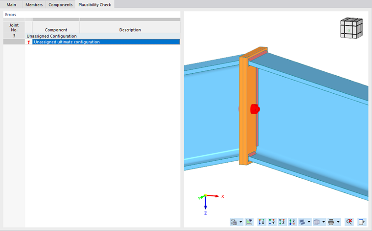
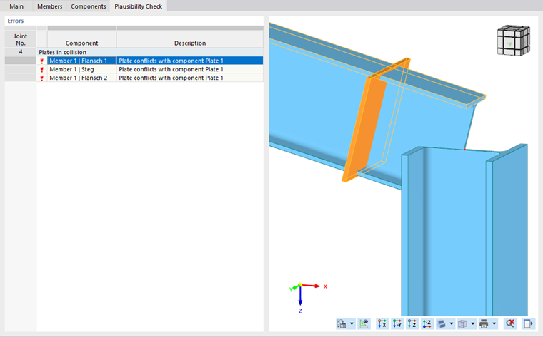
Plate conflicts with component.
The message "Plate conflicts with component X" indicates that the plate or the steel section has been entered incorrectly. To correct the problem, check the entries of the plate component. Adjust the position of the plate in such a way that there is no collision.
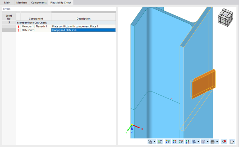
Unapplied plate cut.
This message indicates that the plate cut was not done correctly. In the "Components" tab, you can check the input data of the plate and the plate section. In our example, the angle is too steep, so it is necessary to reduce the "Displacement in z".
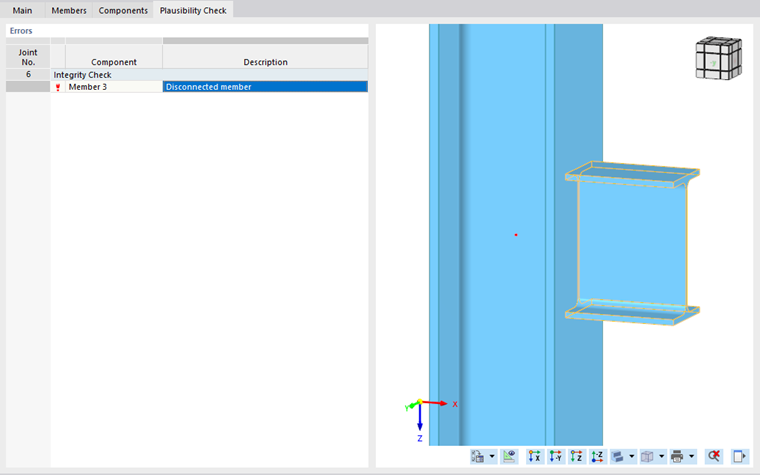
Disconnected member
The plausibility check indicates that a certain member is not connected. In the "Components" tab, you can check the input data, especially that of the weld seam modeling. Activating the weld allows for error-free modeling.
Bolt Group | Wrong horizontal spacing of bolts.
This modeling and the associated error description of the plausibility check concern an incorrect horizontal spacing of bolts. In our example, it is necessary to correct the value of the horizontal bolt spacing in [mm] from 10.0 30.0 100.0 to 15.0 30.0 95.0. Check that the bolts are not touching the edges of the end plate or the weld.

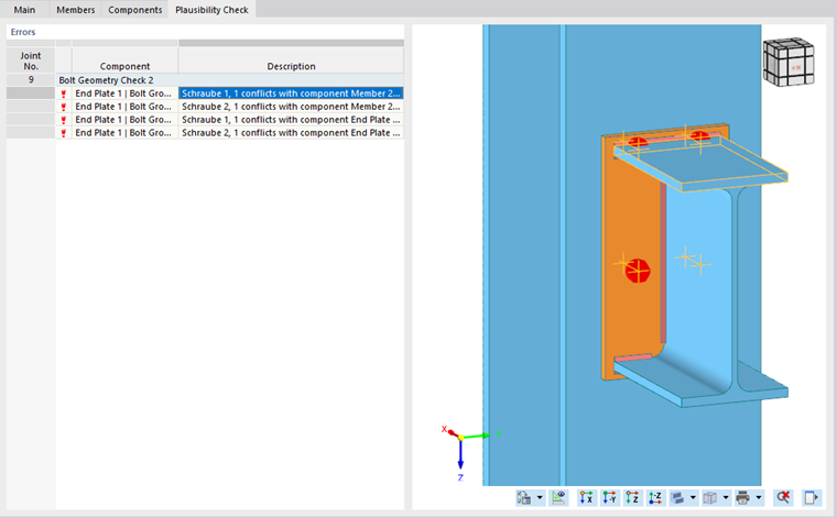
Bolt conflicts with component.
In our example, the top row of bolts collides with the weld and the flange of the connected beam. Check and adjust the bolt spacing in the vertical direction. You can do this in the "Bolts" section for the "end plate".
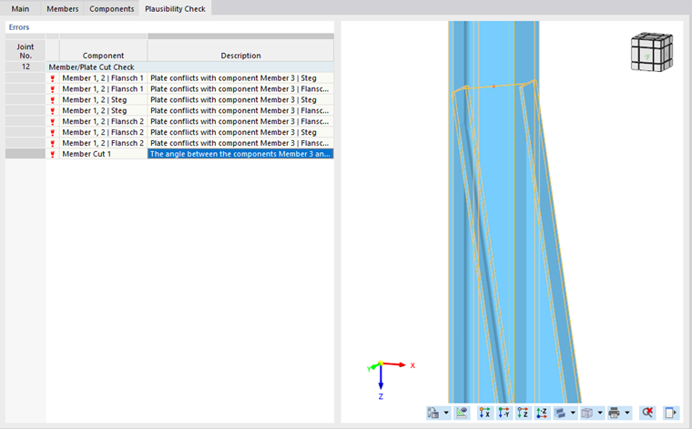
The angle between the components Member X and Member Y is too sharp.
In this example, the plausibility check detects an angle that is too large to carry out the Member Cut component. To correct the error, close the Steel Joint dialog box and edit the member node to ensure error-free modeling. Specify an obtuse angle.
Missing components
With this message, the plausibility check indicates that a component for creating the connection is missing from the members. In this case, it is necessary to insert the end plate joint component. You can create the joint by assigning the members to be connected and the material.

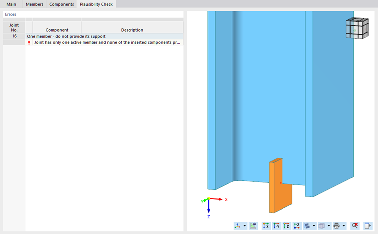
Joint has only one active member, and none of the inserted components supports it.
In the following example to this message, the second member is missing to create a connection. Therefore, select another member.
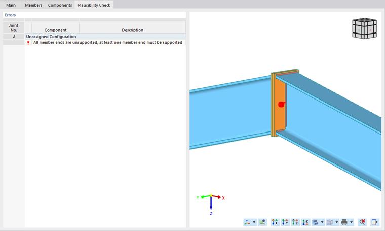
All member ends are unsupported. / All member ends are supported.
The message All member ends are unsupported, at least one member end must be supported or All member ends are supported, at least one member end must be free appears if there is an incorrect entry in the "Members" tab. Check whether at least one member has supported ends . However, not all members may be supported, otherwise there would be no subsequent loading.
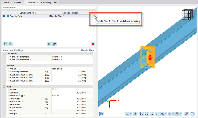
Undefined material
If this message is displayed, no material is assigned to the respective component.
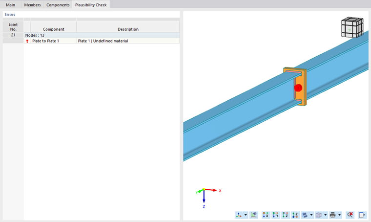
To fix the error, switch to the "Components" tab and assign the material to the component in the "Plate" category. When you move the pointer over the red exclamation mark next to the faulty component, a short description of the problem appears.