If you want to modify the shape of a plate, you can insert a modification component called Plate cut. A plate can be modified by one or more plate cuts.
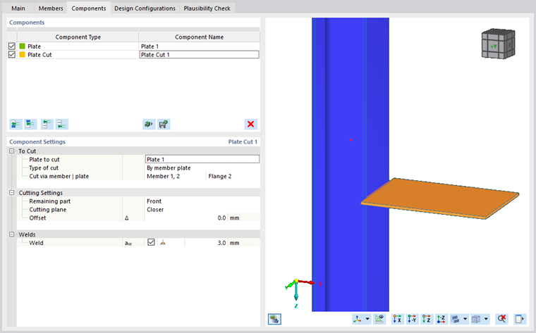
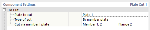
To Cut
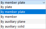
In the first category of the "Component Settings", you can define the plate to be cut, followed by the type of cut. There are five types of cuts: By plate, By member plate, By member, and By auxiliary plane. A more detailed description of particular types of cuts can be found below. The last row determines the reference object that is governing for the cut.
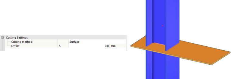
Cutting Settings
The input details differ in some respects, depending on the type of cut.
By Plate
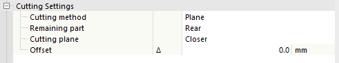
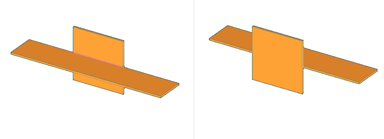
The first line of additional settings for the By plate type of cut controls the Cutting method. The first of both available methods is the Plane, where the cut is made by the closest surface of the reference plate. The latter method, Surface, only cuts the intersection of both plates.
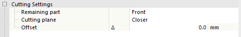
By selecting Plane, two additional options appear. First, it is necessary to specify the Remaining part, that is, the remaining piece of the plate, with the options Front and Rear.
Furthermore, you can select which Cutting plane is the controlling one, whether it is Closer or Farther from the subjected plate side. The default status is Closer, as it is the more common case.
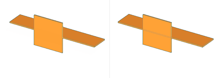
For both cutting methods—Plane and Surface—it is also possible to set an Offset of the cut, where the actual cut is made. Both positive and negative values are allowed.
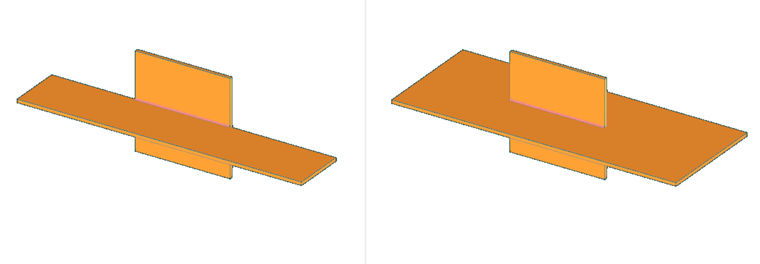
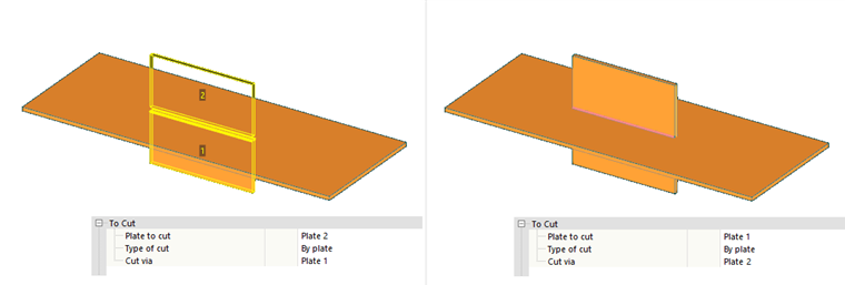
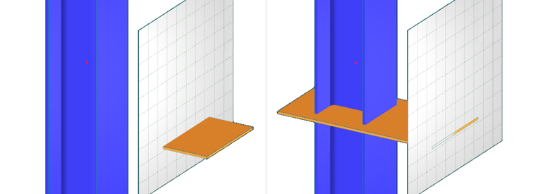
When using the Surface cutting method, the cut plate may be split into several parts. In this case, it is necessary to specify the remaining part. To do so, the additional setting includes a new line where you can select the remaining part by a number that is displayed in the graphics. This option can be seen in the left image below for the reference plate Plate 1, if the cut plate is Plate 2. For comparison, you can see the same setting for the Surface cutting method in the image to the right; only the cut plate and the reference plate are switched. In this case, the cut plate remains in one piece. Therefore, it is not necessary to define the remaining part.
By Member Plate
The By member plate type of cut is similar to the By plate cutting. The difference is that the reference plate has to be a part of a member.
Additional settings for this type of cut are almost the same to those for the By plate type of cut; only the cutting method is left out. First, you should decide whether to keep the Front or the Rear part.
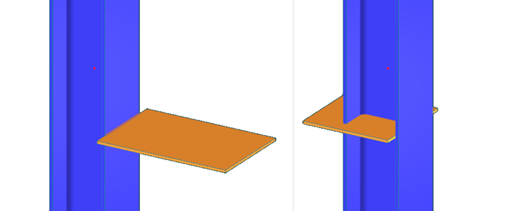
The second option is to define the cutting plane; either the Closer or Farther face of the reference plate.
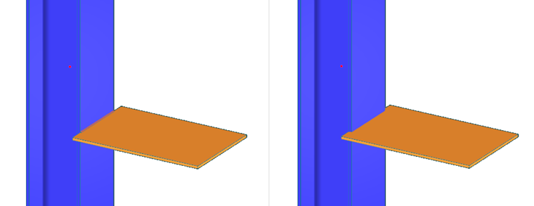
Even for this type of cut, it is also possible to set an Offset of the cut where the actual cut is made, with both positive and negative values allowed.
By Member
Plates can also be cut using a member. The cutting methods Plane, Surface, Bounding box, and Convex hull are available, each with the additional setting Offset. If the cut plate is split into two parts, a new line appears to define the remaining part (just as in the case of the By plate type of cut).
By Auxiliary Plane
The By auxiliary plane cutting plate is similar to the By plate cut with the Plane cutting method. Since the auxiliary plane has no thickness, the Cutting plane option is left out and you only need to specify the Remaining part of the cut. The options are again Front and Rear.
For the By auxiliary plane type of cut, you can also select an Offset of the actual cut from the auxiliary plane by entering positive or negative values.
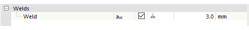
Welds
In cases where the cut creates a contact between plates, you can define a weld in the Welds category. The definition contains a check box that controls whether to create a weld, a combo box for the weld type, and the weld thickness for the fillet weld.