The Main tab manages general settings related to the members of the joint and the design configuration for the design checks.
Assignment of Members
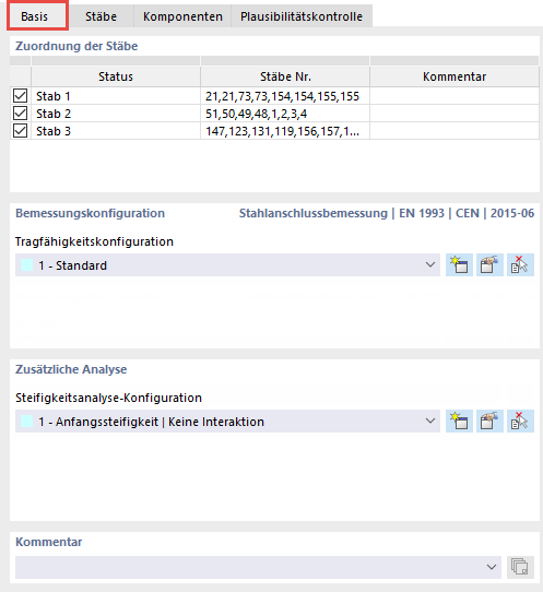
As soon as you select a node for the design, the program assigns all members connected to this node.
You can use the check boxes in the first column to remove members from the design:
![]() . The Status corresponds to the type of grouping: If there are several nodes to be designed, all members with same properties are combined and have the corresponding position in the structural model. The description in the status, where you can also type an individual name, will be used later for the components. The Members No. column lists the member numbers used in the RFEM or RSTAB model. You can optionally enter a Comment on the respective status in the last column.
. The Status corresponds to the type of grouping: If there are several nodes to be designed, all members with same properties are combined and have the corresponding position in the structural model. The description in the status, where you can also type an individual name, will be used later for the components. The Members No. column lists the member numbers used in the RFEM or RSTAB model. You can optionally enter a Comment on the respective status in the last column.
Design Configuration
In this section, you can select the ultimate configuration to be used from the list, create a new one,
![]() , edit it,
, edit it,
![]() or use it in the graphic from another joint
or use it in the graphic from another joint
![]() .
.
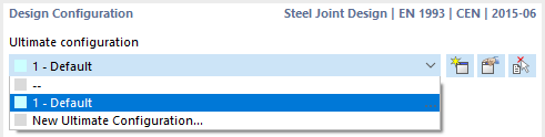
The design configurations are explained in the chapter Ultimate Configurations.
Additional Analysis
In this section, you can select the stiffness analysis configuration to be used from the list, create a new one,
![]() , edit it,
, edit it,
![]() or transfer it in the graphic from another joint
or transfer it in the graphic from another joint
![]() .
.
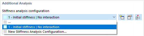
The stiffness analysis configurations are described in Chapter Stiffness Analysis Configurations.
Comment
You can add a comment to each joint, which is then displayed after the joint name.
Graphic Window
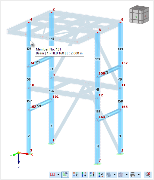
In the dialog graphic, all nodes to be designed are displayed with the connected members, provided that you have not deactivated them in the "Assignment of Members" section.
When you move the mouse over a node, the number and coordinates of the node are displayed. If you move the cursor over a member, you get information about the member number, cross-section, material, and member length.