


In the Stiffness Analysis Configuration dialog, you can define basic settings for determining the stiffness of a steel joint. These settings are applied to the Submodel that is generated in the background for the calculation.

The 'List' on the left shows all configurations in the model. With the
![]() button, you can create a new configuration based on the default values of the design standard defined in the
Base Data
. Alternatively, use the
button, you can create a new configuration based on the default values of the design standard defined in the
Base Data
. Alternatively, use the
![]() button to copy an existing configuration and then adjust the design parameters. The
button to copy an existing configuration and then adjust the design parameters. The
![]() button deletes the configuration selected in the list.
button deletes the configuration selected in the list.
Base
The Base tab manages important 'Design Parameters' for the stiffness analysis.
Type of Stiffness Analysis
Specify whether to calculate the 'Initial stiffness' Sj,ini or to generate a 'Stiffness diagram'.
Joint-Structure Interaction
The 'Generate hinges in global model' check box provides the option to apply the results of the stiffness analysis to the RFEM model in the form of member hinges. RFEM generates hinges with the spring stiffnesses of the joints and assigns them to the members.
Classification by Stiffness
The 'Frame with bracing systems' check box controls whether it is a bracing system that reduces the horizontal displacement by at least 80%. Checking this option ultimately affects the coefficient Kb, which is then only 8 instead of 25.
Analysis
The list for the Analysis Type provides a selection between linear static analysis and second-order analysis (PΔ).
If the calculation does not converge with the default setting of a maximum of 100 iterations, you should increase the 'Maximum number of iterations' accordingly. For more information, see the Static Analysis Settings chapter in the RFEM manual.
For better convergence and to avoid instabilities in nonlinear systems, it is recommended to set several Load Steps. However, a large 'Number of load steps' has a negative effect on the calculation time.
Modeling
The 'Member length factor' controls the length of the substitute model of the member. The larger value from the length and width of the circumscribed rectangle is multiplied by the value defined here.
Mesh
The last category offers various setting options for the FE mesh, as different mesh densities may be required depending on the joint type. You can specify the minimum and maximum element size 'Generally'.
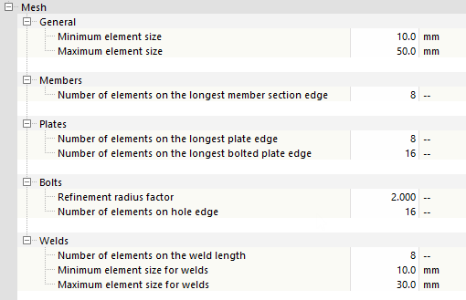
Furthermore, you can adjust the number or size of the finite elements for various components – members, slabs, bolts, welds – to the geometry of the joint. The larger the number of elements or the smaller their size, the finer the mesh.
The default settings of the design parameters should be suitable for most cases and also provide sufficiently accurate results with regard to the calculation time.
