


A stub is a special member component for connecting two objects, for example to connect a beam to a column using a different cross-section. This fictitious member is only considered in the connection design, but not in the model. The connection to the other members is made via welds and fasteners.

Objects to connect
The first category of component settings manages the member data.
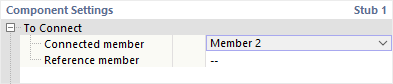
Specify which of the members connected at the node is relevant as the 'Connected member' for the stub. This is usually a beam. The 'Reference member' is optional. However, it is useful if a beam is connected at an angle: The inclination angle is then automatically applied to bevel the stub.
Stub section
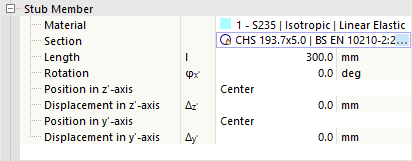
In this category, define the properties of the stub member. Select the appropriate material from the defined materials, or use the
![]() button to create a new material. Then, define the cross-section. Here, too, use the
button to create a new material. Then, define the cross-section. Here, too, use the
![]() button in the input field to select the section in the RFEM library.
button in the input field to select the section in the RFEM library.
In the 'Length' input field, specify the length of the stub. If this member is to be rotated or placed with an offset, define the 'Rotation' or specify the 'Position' using the selection lists and offset vectors. In the work window, you can use the
![]() button to switch to the symbol view, which illustrates the parameters.
button to switch to the symbol view, which illustrates the parameters.
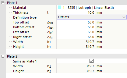
Plate 1 / Plate 2
The plates in the transition area between the connected member and the stub can establish the connection of the two sections. 'Plate 1' is arranged on the connected member, 'Plate 2' on the stub.
Select the appropriate material from the defined materials or use the
![]() button to create a new material. Then specify the thickness of the plate.
button to create a new material. Then specify the thickness of the plate.
You can define the plate geometry via 'Offsets' or 'Dimensions and position'. Select the corresponding option in the list.
Offsets
The plate size results from the cross-section dimensions of the connected member. Use the 'Offset' in the four directions to specify how far the plate extends beyond the boundary frame of the cross-section. The resulting width and height are indicated in the last two rows; these values cannot be changed.
Dimensions and position
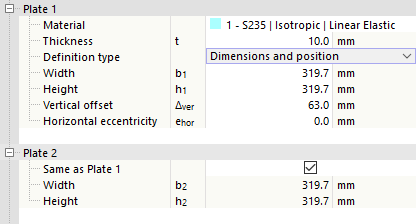
You can specify the size of the plate directly. The position refers to the cross-section of the connected member or stub, where the vertical offset is measured from the top edge (cross-section side of the negative z-axis) and the horizontal eccentricity from the center of gravity of the member cross-section.
Bolts
If you do not define the bolts separately as Fastener objects, you can define their properties in this category.
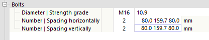
In the lists, select the 'Diameter' and the 'Strength class' of the bolts.
Then specify the 'Number' and the 'Horizontal distance' and 'Vertical distance' of the bolts. Here, too, the
![]() button in the work window is helpful for switching to the symbol view of the parameters.
button in the work window is helpful for switching to the symbol view of the parameters.
Detailed explanations about the bolt definition can be found here.
Welds
The last category controls which welds are used to connect the plates to the member end or stub end. If you deactivate one of the check boxes, no weld is arranged on the corresponding object.

If you click in the column next to the check box, you can open a list for selecting the weld types. Various types of fillet welds and butt welds are available for selection. For fillet welds, specify the thickness of the weld.