


All components of the joint are managed in the Components tab.
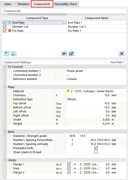
Components
In the first column, you can set components to be active
![]() or inactive
or inactive
![]() using the check boxes. The type of the component is displayed in the Component Type column. In the Component Name column, you can adjust the automatically assigned designation of the component. This name will be used later for the design and the results.
using the check boxes. The type of the component is displayed in the Component Type column. In the Component Name column, you can adjust the automatically assigned designation of the component. This name will be used later for the design and the results.
Inserting Components
You can insert a new component at the start
![]() or at the end
or at the end
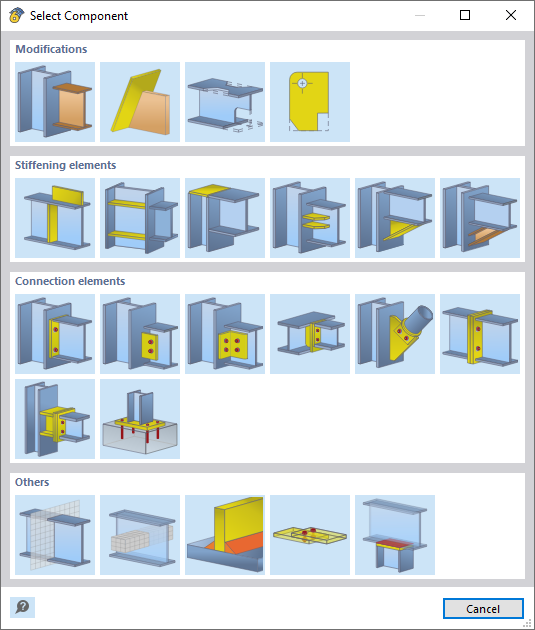
![]() of the table. By clicking one of the buttons, you can open the "Select Component" dialog box where you can select the component in four main categories.
of the table. By clicking one of the buttons, you can open the "Select Component" dialog box where you can select the component in four main categories.
Use the
![]() button to insert the components from a library. This option is described in the chapter Templates for Steel Joints. If you have created your own joint, you can save it as a template
button to insert the components from a library. This option is described in the chapter Templates for Steel Joints. If you have created your own joint, you can save it as a template
![]() together with all components.
together with all components.
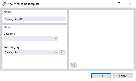
Enter a designation as the "Name". You can assign the connection to a "Category" that is already entered in the library. If you do not select any entry in the list, the joint is stored in a user-defined category. Finally, define the "Subcategory" or create a new type
![]() .
.
Edit Component
You can use the
![]() button to delete the selected component again.
button to delete the selected component again.
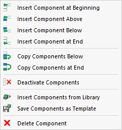
Shortcut Menu
The shortcut menu of a component allows you to copy the selected component to below
![]() or to the end of the list
or to the end of the list
![]() .
.
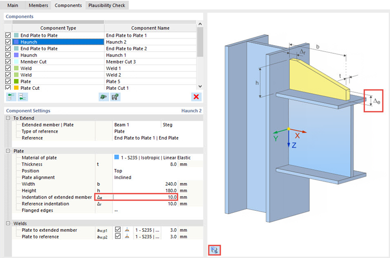
Component Settings
In this section, the properties and definition criteria of the component selected in the "Components" table above are defined. They are described in detail in the chapter Components.
Graphic Window
The component selected in the table is highlighted in the selection color in the dialog graphic. When you move the mouse over a member, its designation ( "status" ) is displayed. The same applies to the individual components.
Use the
![]() button below the graphic to switch between a symbol display with additional information and the actual view. The symbol display is matched to the input parameter selected in the "Component Settings" table. The graphics window then displays the input-specific information.
button below the graphic to switch between a symbol display with additional information and the actual view. The symbol display is matched to the input parameter selected in the "Component Settings" table. The graphics window then displays the input-specific information.
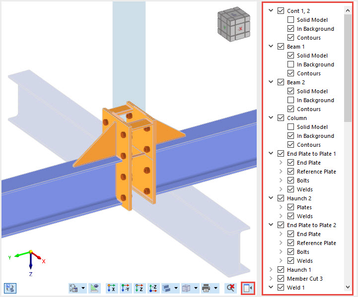
A navigator is also available to control the display, which you can expand using the
![]() button. Its tree structure contains all members and components, including subcomponents existing in the selected joint. You can show or hide them individually for the display or display them as a "Solid Model", "In Background", and also with or without "Contours".
button. Its tree structure contains all members and components, including subcomponents existing in the selected joint. You can show or hide them individually for the display or display them as a "Solid Model", "In Background", and also with or without "Contours".
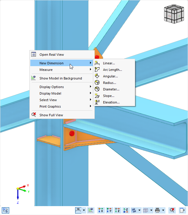
Dimensions
A function with which you can add dimensions to the steel joint is available in the shortcut menu of the graphic window.
Notes
The shortcut menu also provides the option to create notes. These refer to a snap point and can thus be flexibly assigned to any component. This allows you to store additional information about individual components directly in the model. Detailed information on creating notes can be found in the online manual of the main program RFEM 6.
