


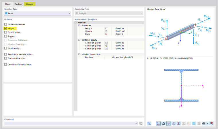
The Main tab manages the basic member parameters. If you select a check box in the 'Options' section, another dialog tab is usually added. There, you can define the details.
Member type
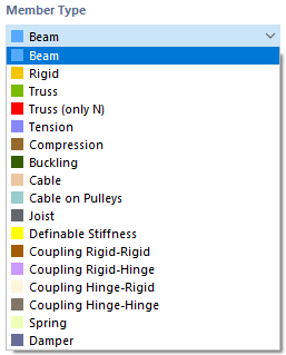
The member type controls how internal forces can be absorbed or which properties are assumed for the member. Various member types are available for selection in the list.
Beam member
A beam is a bending-resistant member that can transfer all internal forces. A beam member has no hinges on its member ends. This member type can be loaded by all load types.
Rigid member
A rigid member couples the displacements of two nodes by a rigid connection. It therefore principally corresponds to a Coupling. This allows you to define members with very high stiffness, taking into account hinges, which can also have spring constants and nonlinearities. There are hardly any numerical problems because the stiffnesses are adapted to the system.
Internal forces are output for rigid members if you activate the Results for Couplings in the Navigator - Results below in the 'Members' category.
The following stiffnesses are applied for rigid members:
| Axial stiffness E · A | 1013 · ℓ [SI unit] with ℓ = member length |
| Torsional stiffness G · IT | 1013 · ℓ [SI unit] |
| Bending stiffness E · I | 1013 · ℓ3 [SI unit] |
| Shear stiffness GAy / GAz (if activated) | 1016 · ℓ3 [SI unit] |
Truss member
A truss member corresponds to a beam member with moment hinges at both ends. Additionally, the rotation about the longitudinal axis is released at the member start by a hinge φx. For this member type, bending and torsional moments are output from the loads of the member.
Truss member (only N)
This type of truss member with stiffness E ⋅ A is able to absorb axial forces in the form of tension and compression. Only nodal internal forces are output. The member displays a linear internal force distribution, provided no single load acts on the member. No moment distribution that could result from self-weight or a line load is output. The nodal forces, however, are calculated from the member loads, thus ensuring correct load transfer.
Buckling-Restrained Brace
The type Buckling-restrained brace allows you to model a member with a steel core (flat bar or cross-shaped cross-section) and a concrete-filled casing in a square or round hollow section. It is used especially in the USA for stiffening buildings at risk of earthquakes.
The steel core is movable in the concrete casing without bond. Under compression, "micro-buckling" with high eigenmodes occurs, as the casing prevents global buckling of the entire member.
Only the steel core is considered for the stiffness of the member, whereas for the automatic self-weight, the concrete casing with the outer steel shell is also considered.
Tension member
A tension member can only absorb tension forces. The member type corresponds to a 'Truss member (only N)' that fails under a compressive force.
The calculation of a framework with tension members is iterative: In the first step, the internal forces of all members are determined. If tension members receive a negative axial force (compression), another iteration step starts. The stiffness components of these members are no longer considered – they have failed. This process continues until no more tension members fail. A system can become unstable due to the failure of tension members.
Compression member
A compression member can only absorb compressive forces. The member type corresponds to a 'Truss member (only N)' that fails under a tension force. Failing compression members can lead to an unstable system.
Buckling member
A buckling member corresponds to a 'Truss member (only N)' that absorbs unlimited tension forces, but compressive forces only up to reaching the critical force. For Euler case 2, this force is determined as follows:
This member type can often be used to avoid instabilities that arise from buckling of truss members in a nonlinear calculation according to second-order or large deformation analysis. If you replace these (realistically) with buckling members, the critical load is increased in many cases.
Cable member
A cable can only be subjected to tension. This allows you to model cable chains by an iterative calculation according to the large deformation analysis, considering longitudinal and transverse forces.
Cables are suitable for models where large deformations with corresponding changes in internal forces can occur. For simple bracing, such as on a canopy, tension members are perfectly sufficient.
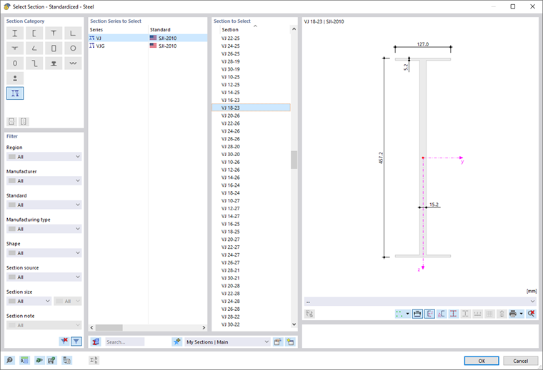
Virtual Joist
This member type allows you to apply the cross-section properties for Open Web Steel Joists, which the Steel Joist Institute has stored in so-called "Virtual Joist" tables. These Virtual Joist profiles represent equivalent wide-flange beams that come very close to the chord area, effective moment of inertia, and weight. The joist is thus replaced by a member with a virtual cross-section. This allows you to simulate complex structural units, such as a roof truss, in the overall system.
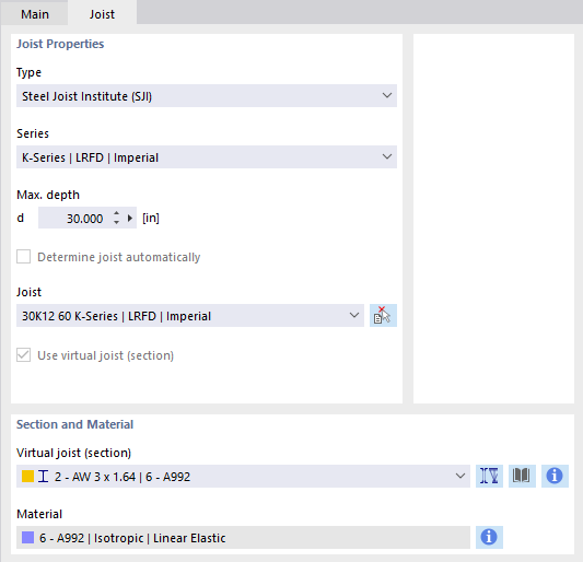
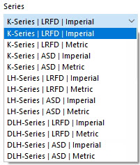
Select the 'Series' of the virtual joist in the list.
In the 'Virtual Joist' list, you can then define the exact type.
The
![]() button in the 'Cross-Section and Material' section allows you to import the virtual joist from the cross-section library.
button in the 'Cross-Section and Material' section allows you to import the virtual joist from the cross-section library.
Stiffness
With this member type, you can use a member with user-defined stiffnesses. The stiffness parameters are to be defined in the 'New Member Stiffness' dialog (see Chapter Member Stiffnesses).
Coupling
A coupling rod is a virtual, very stiff member with rigid or hinged member ends. There are four options available for coupling the degrees of freedom of the start and end nodes 'Fixed' or via a 'Hinge'. Couplings allow you to model special situations for force and moment transfer. The axial and shear forces or torsional and bending moments are transferred directly from node to node.
Spring
A spring member offers the possibility to represent linear or also nonlinear spring properties with definable effective ranges. For a spring member, you only need to define the member length Lz in the 'Cross-Section' tab, not a cross-section: The stiffness of the member results from the spring parameters that you define in the 'New Member Spring' dialog (see Chapter Member Springs).
Damper
A damper corresponds in principle to a spring member with the additional property 'Damping coefficient'. This member type extends the possibilities for dynamic analyses according to the Time history analysis.

As with a spring member, you only need to define the member length Lz in the 'Cross-Section' tab, not a cross-section. The stiffness of the member results from the spring parameters that you define in the 'New Member Spring' dialog (see Chapter Member Springs). You can control the damping properties via the damping coefficient X.
Options
In this section, you can define further member properties via the check boxes.
Nodes on Member
With one or more nodes on the member, you can divide the member into segments without splitting the member (see Chapter Nodes ).
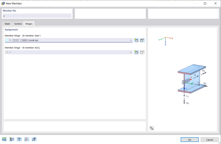
Hinges
You can arrange hinges on a member to control the transfer of internal forces at the end nodes (see Chapter Member End Hinges). The input is blocked for specific member types, since internal hinges already exist. You can assign hinges separately to the 'Member start i' and the 'Member end j'.
Eccentricities
Eccentricities offer the possibility of connecting the member eccentrically at the end nodes (see Chapter Member Eccentricities). You can assign eccentricities separately to the 'Member start i' and the 'Member end j'.
Support
You can assign a support to the member that is effective over its entire length. The degrees of freedom and spring stiffnesses are to be defined in the support conditions (see Chapter Member Supports).
Transverse Stiffeners
Transverse stiffeners on the member have an influence on the warping stiffness of the member. They affect the calculation with torsional warping considering seven degrees of freedom (see Chapter Member Transverse Stiffeners).
Nonlinearity
You can assign a nonlinearity to the member. The nonlinear properties are to be defined as member nonlinearities (see Chapter Member Nonlinearities).
Result Intermediate Points
With result intermediate points, you can control the table output of results along the member. The division points are to be defined in the 'New Member Result Intermediate Point' dialog (see Chapter Member Result Intermediate Points).
End Modifications
With end modifications, you can graphically adjust the geometry of the member at its ends. This allows you to prepare projections, shortenings, or bevels for the rendered display.
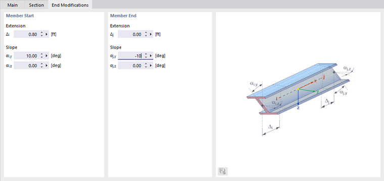
'Extension': You can define an 'Extension' for the member start and the member end. A negative value Δ acts as a shortening.
'Skew': With a skew, you can bevel each member end. Inclination angles about the two member axes y and z are possible. A positive angle causes a clockwise rotation about the respective positive axis.
Deactivate for Calculation
If you select this check box, the member, including loading, is not considered in the calculation. This allows you to investigate how the structural behavior of the model changes when certain members are not effective. The members do not need to be deleted; the loads are also maintained.
