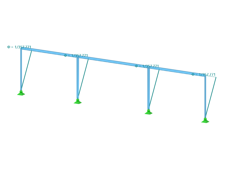
Member imperfections offer the possibility to display effects of imperfections by means of equivalent pre-deformations in the form of inclinations and precambers of members. They are taken into account in the calculation by equivalent loads.

Categories
Member imperfections can be modeled in different ways. The settings in the "Categories" dialog section control the entries to be made in the "Parameters" dialog section.
Imperfection Type
Select the type of imperfection from the list.
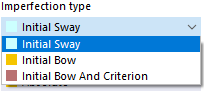
An inclination is represented by an "Initial Sway"; an "Initial Bow" represents the magnitude of an initial deflection of the member. The "Initial Bow and Criterion" option allows for defining a precamber depending on the inclination. Depending on the selection and definition type, you can define the values of inclinations or precambers in the "Parameters" dialog section.
An initial bow is represented by a normal force distribution on the internal member nodes.
Definition Type
The list offers various options to apply the imperfection by a user-defined setting or according to standard specifications.
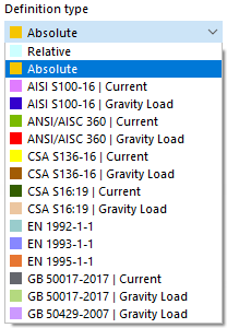
Depending on the selection, you can define the values for inclinations or precambers in the "Parameters" dialog section by means of relative (related to the member length) or absolute values, or standard-specific parameters. That dialog section adapts dynamically to the definition and imperfection types. The types and parameters are illustrated in the dialog graphic.
Coordinate System
You can relate the direction of the imperfection to the following coordinate systems of the member cross-section:
- Local xyz: Input axes of the cross-section that correspond to the principal axes for symmetrical cross-sections
- Principal xuv: Principal axes of a cross-section
Imperfection Direction
In the list, select the axis direction in which the imperfection acts.
.png)
Parameters
In this dialog section, you can define the values for inclinations and precambers. The input text boxes correspond to the imperfection type and the definition type. The image New Member Imperfection shows the general parameters for the relative input of an inclination.
When setting the EN 1993-1-1 definition type, it is necessary to specify the parameters shown in the following image.
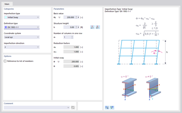
Based on the entered values, reduction factors and initial sways are calculated in accordance with standards. If the buckling curve of a member is not known (because of a built-up cross-section, for example), the buckling curve d is applied as the most unfavorable value.
If you have specified the ANSI/AISC 360-16 | Gravity Load definition type, the parameters are as shown in the following image.
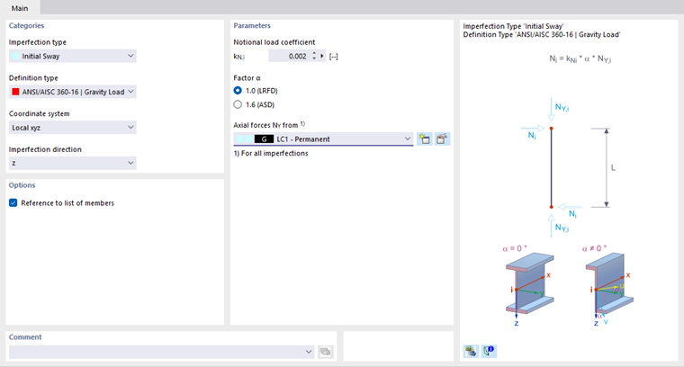
If you have defined the Initial Bow and Criterion imperfection type, you can select the "Activity criterion" from a list.
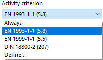
The initial bow can always become effective, or from a certain slenderness ratio according to the standard, or from a user-defined member coefficient.
Options
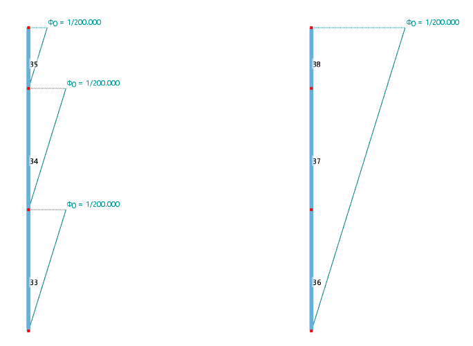
The "Reference to list of members" check box controls whether the imperfection acts separately on each member, or as a whole on all members to which you assign the imperfection. The approaches are compared in the following image.
The “Refer distance to the member end” check box only shows its effect if the imperfection is not applied over the total length of the member (see the following paragraph). You can then specify the distances A and B in relation to the member end in the “Parameters” section.
In most cases, the “Imperfection over total length of member” applies. If you deactivate the check box, you can specify the distances of the imperfection in the “Parameters” section. Distance A describes the distance of the beginning of the imperfection, Distance B that of the end of the imperfection. Both distances refer to the member start.

Use the
![]() button to switch between relative and absolute input of the distances.
button to switch between relative and absolute input of the distances.