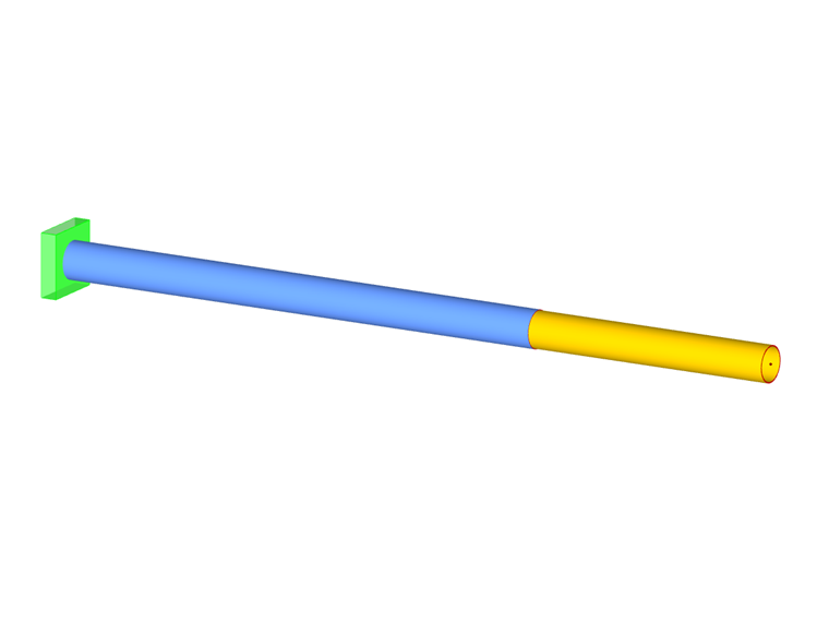
A member hinge limits the internal forces and moments that are transferred from one member to others. Hinges can only be arranged at member ends, not at locations along the member.
Some member types are already provided with hinges: A truss, for example, does not transfer moments, and a cable member transfers neither moments nor shear forces. It is impossible to assign any hinges to such member types. The input is blocked.
Main
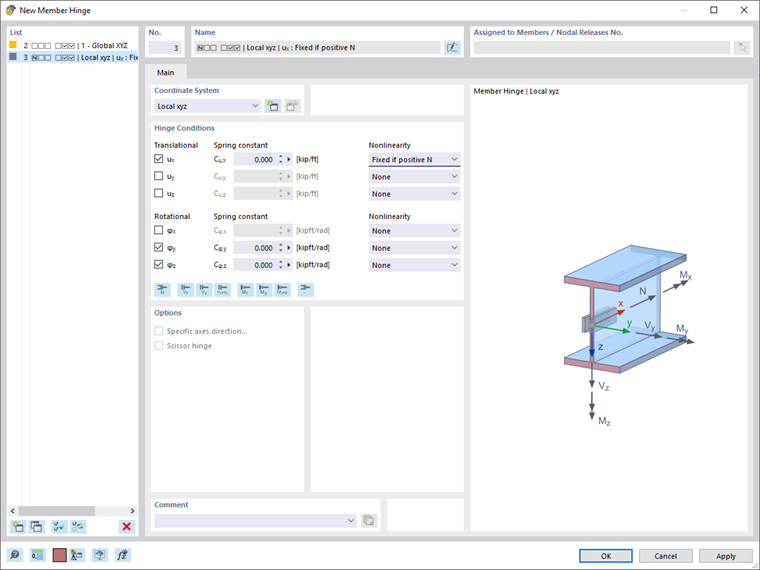
The Main tab manages the basic hinge parameters.
Coordinate System
A member hinge can be related to one of the following axis systems:
- Local member axis system x,y,z
- Global coordinate system X,Y,Z (optionally as a scissor hinge)
- User-defined axis system U,V,W
Generally, hinges are related to the local member axis system. However, scissor hinges (see the image Member Crossing) are only possible in the global or a user-defined axis system.
Hinge Conditions
The hinge conditions are divided into "Translational" and "Rotational" degrees of freedom. The former describe the displacements in the direction of the local or global axes; the latter describe the rotations about these axes.
To define a hinge, select the check box for the respective axis. The check mark indicates that the member's displacement in or rotation about the corresponding direction is possible. The constant of the translational or rotational spring is then set to zero. You can adjust the "Spring constant" anytime in order to model an elastic hinge. Enter the spring stiffnesses as design values.
In the Nonlinearity column, you can specifically control the transfer of internal forces and moments for each component. Depending on the degree of freedom, suitable entries are available for selection in the list of nonlinearities.
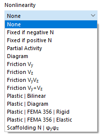
Fixed if internal force is negative or positive
This allows you to control easily whether only positive or negative forces or moments are transferred at the member end. For example, a ux-hinge with the nonlinearity "Fixed if positive N" causes tension forces (positive) to be transferred at the member end, but compression forces (negative) are not transferred. Thus, the hinge is effective for negative axial forces.
In the case of a local coordinate system, the internal forces and moments refer to the local xyz-member axis system.
When you select a different nonlinearity, you can define the parameters in the Partial Activity, Diagram, Friction or Scaffolding Diagram tabs.
Options
A "Scissor hinge" is available in the global or user-defined coordinate system. This kind of hinge allows you to model intersections of continuous members.
Example
Four members are connected to a node. The members transfer moments in their "continuous direction", but not to the other member pair. Only axial and shear forces are transferred in the node.
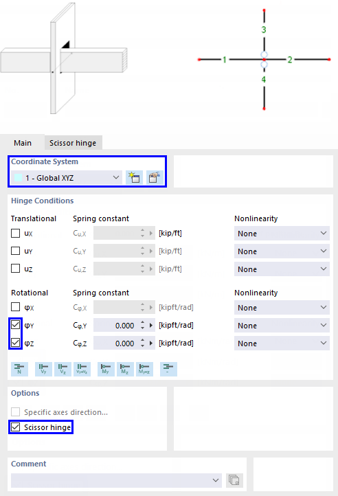
Assign the hinge either to Member 3 and 4, or to Member 1 and 2. The other crossing member pair does not receive a hinge.
Partial Activity
The Partial Activity of a hinge component is available as a nonlinear property of the member hinge (see the image Selecting Hinge Nonlinearity).
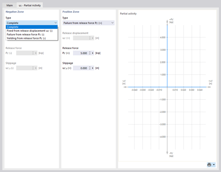
Define the effect of the hinge for both the "Negative Zone" and the "Positive Zone". The "Type" list offers various criteria for the effectiveness of the hinge.
- Complete: Due to the hinge, displacement or rotation is possible to the full extent.
- Fixed from release displacement/rotation: The hinge is only effective up to a certain displacement or rotation. If the limit is exceeded, a fixed connection or restraint becomes effective.
- Tearing from release force/moment: The hinge is effective only up to a certain force or moment. If the limit is exceeded, the hinge fails and no longer transfers the internal force or moment.
- Yielding from release force/moment: The hinge is effective only up to a certain force or moment. If it is exceeded, the strains still increase, but not the internal force or moment.
- Spring ineffectiveness: In the case of a hinge with spring stiffness, the hinge component is not effective.
Most hinge types can be combined with a "Slippage", which means that the hinge becomes effective only after a certain displacement or rotation.
Diagram
The Diagram of a hinge component is available as a nonlinear property of the hinge (see the image Selecting Hinge Nonlinearity).
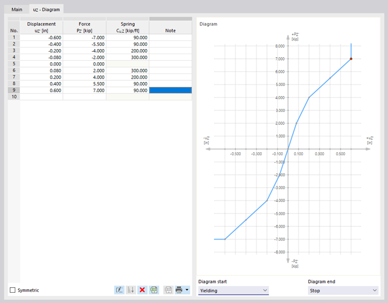
Define the number of definition points for the work diagram by entering the corresponding values in the "Displacement" or "Rotation" column. Then, in the "Force" or "Moment" column, you can assign the x-coordinates of the displacements or rotations with the hinge forces or moments.
If the order of definition points is incorrect, you can sort the entries in ascending order by using the
 button.
The following criteria are available for selection for the "Diagram start" and the "Diagram end":
- Tearing: The hinge is only effective up to the maximum value of the force or moment. If it is exceeded, the full hinge effect is reached. Internal forces and moments are no longer transferred.
- Yielding: The hinge is only effective up to the maximum value of the force or moment. If it is exceeded, the strains still increase, but not the internal forces or moments.
- Continuous: Beyond the definition range, the spring constant of the last step is applied.
- Stop: The allowable deformation is limited to the maximum value of the displacement or rotation. If it is exceeded, the hinged effect is suspended and a fixed connection or restraint becomes effective.
Friction
The "Nonlinearity" list offers four options to define the Friction of a translational hinge depending on another hinge component (see the image Selecting Hinge Nonlinearity).
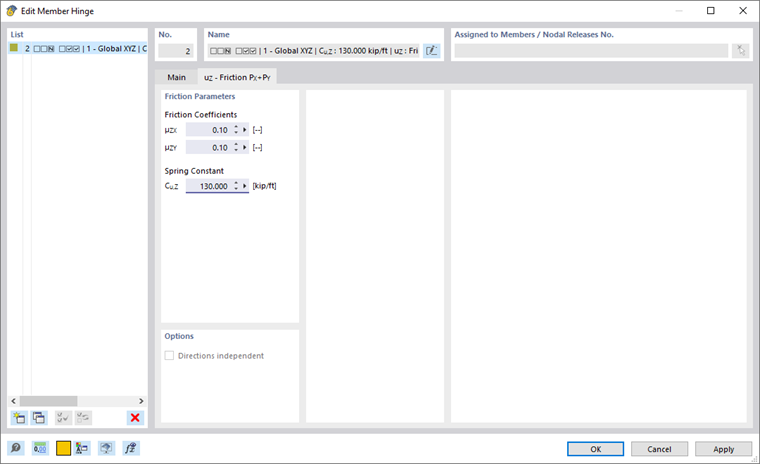
The transferred hinge forces are related to the axial or shear forces acting in another direction. Depending on the selection in the "Main" tab, the friction depends on only one or two support forces. The following correlation exists between the friction force of the hinge and the axial or shear force:
Plastic
Plastic hinge properties are important for Pushover Analysis. With the Plastic option of a nonlinearly acting hinge component, four possibilities are available for selection (see the image Selecting Hinge Nonlinearity):
- Bilinear
- Diagram
- FEMA 356 | Rigid
- FEMA 356 | Elastic
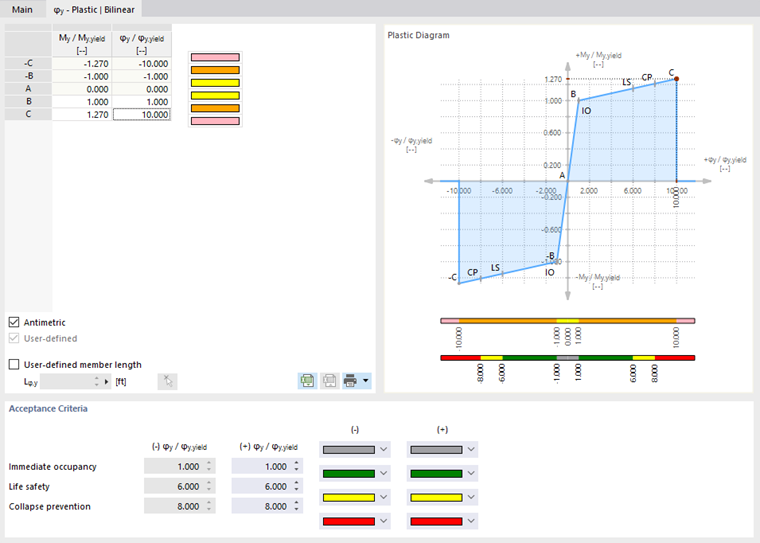
In the columns "Internal force" / "Internal force"yield and "δ / δyield" or "φ / φyield", define the properties of the plastic areas. With a value for My / My,yield of 1.27, for example, the cross-section begins to yield when exceeding the plastic moment. If 127% of the plastic resistance is exceeded, the member fails.
The plastic limit internal forces are determined automatically from the cross-section properties of the member.
The member length affects the stiffness calculation of the plastic hinge. Usually, it is recognized automatically from the lengths of the members to which the hinge is assigned. If necessary, you can specify a "User-defined member length" for the hinge.
Acceptance Criteria
In the lower dialog section, you can define the limit values of the yielding criteria to be applied for the safety of the building. They are described, for example, for structural steel components in Table 5-5 of FEMA 356 (ASCE standard) [1]. Thus, at a value of 6,000 for φ / φyield, the critical value for "Life safety" is reached as soon as the plastic deformations become six times greater than those that occur when the yield point is reached.
The areas of the acceptance criteria are also shown in the diagram.
For one of the two plastic FEMA options, the acceptance criteria are preset according to the specifications of the US standard. You can adjust them, as needed, by selecting the "User-defined" check box.
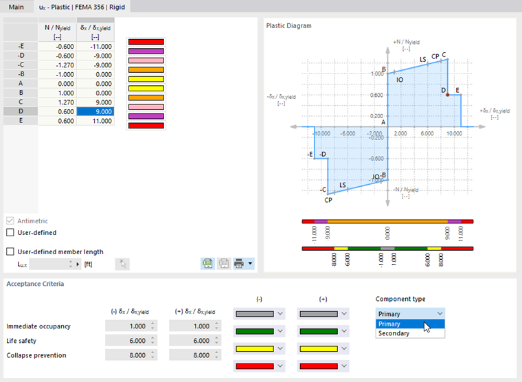
Specify the "Component type" in the list. The acceptance criteria for primary and secondary components are described in Table 5-5 of [1].
The technical article Plastic Hinges in RFEM 6 describes how to use a plastic hinge for a pushover analysis.
Scaffolding Diagram
The Scaffolding Diagram of a hinge component is available as a nonlinear property of the hinge (see the image Selecting Hinge Nonlinearity). This allows you to model the mechanical effect of a connected tube joint with an inner pipe end (stub) between two members. Depending on the compression state at the member end, the equivalent model transfers the bending moment via the overpressed outer pipe and, due to the positive connection, additionally via the inner pipe stub.
You can set the hinge properties separately in the "Scaffolding Diagram | Inner Tube" and "Scaffolding Diagram | Outer Tube" tabs.
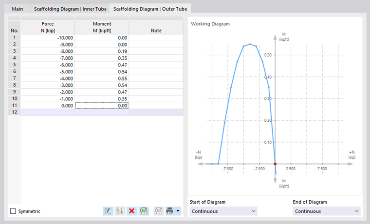
The options described in the Diagram dialog section are available for defining the corresponding parameters.