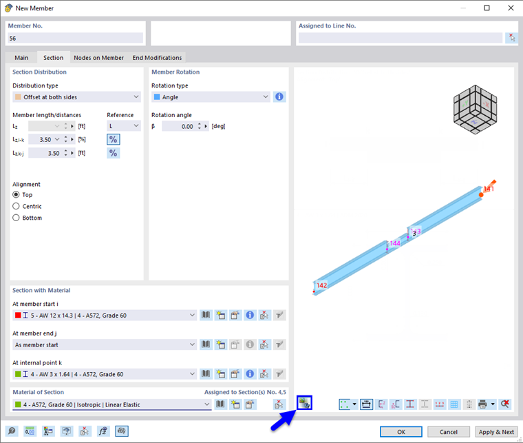
Assign the cross-section in the Section tab. In this dialog tab, you can define the section distribution and arrange a member rotation.
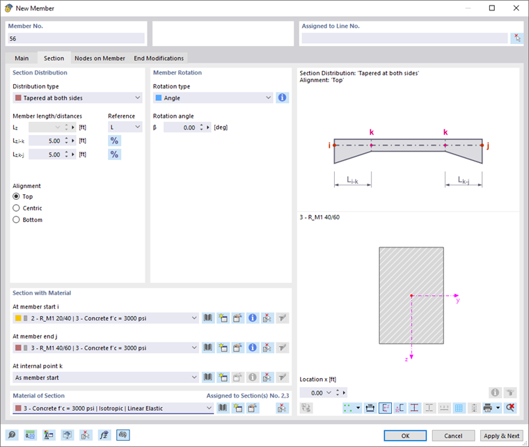
Section Distribution
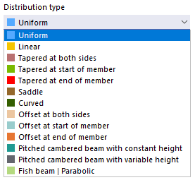
The section distribution controls the shape of the cross-section along the member. With the "Uniform" default setting, a constant distribution over the entire member length is assumed. The list offers various options for tapered distributions or varying shapes changing in sections.
In the text boxes for "Member length/distances", you can define the points for the areas to be defined. The parameters of the selected distribution are shown in the symbolic graphic on the right. You can use the
![]() button to switch between the relative and absolute input of lengths. Then, you have to assign the cross-sections for the individual areas by specifying the settings in the Section with Material section.
button to switch between the relative and absolute input of lengths. Then, you have to assign the cross-sections for the individual areas by specifying the settings in the Section with Material section.
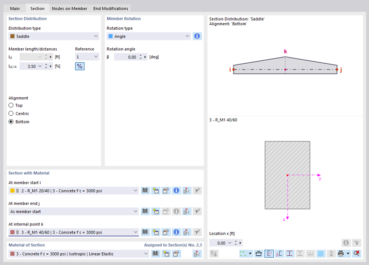
If the cross-section distribution is not uniform, you can adjust the "Alignment" of the top and bottom edges. The effect of the three options is also displayed in the symbolic graphic.
Once you have defined the start and end nodes, you can check the arrangement of the cross-sections graphically using the
![]() button.
button.
Taper from Parameterized Sections and RSECTION Cross-Sections
For both library and RSECTION cross-sections, please note that the difference in the angles between the individual taper cross-section parts must be less than 0.1 rad (corresponds to ≈ 5.73°). The position of the cross-section parts of the start and end cross-sections must therefore only show slight differences; otherwise there is no longer a planar surface in the member diagram. For example, there is no linear distribution of the taper for the following start and end section.

For a taper consisting of RSECTION cross-sections, the end section must be a copy of the start section. Do not add or delete any geometric objects, such as points or elements.
Glued-Laminated Timber Beam
Various design options are available in the list for glued-laminated timber beams (see the image Selecting Cross-Section Distribution):
- Curved
- Pitched cambered beam with constant height
- Pitched cambered beam with constant height
- Fish beam
You have to enter the specifications in two tabs. In the "Section I" tab, you define the general layout of the beam, and you specify whether it has an "Asymmetric layout" or if "Cantilevers" exist on the member.
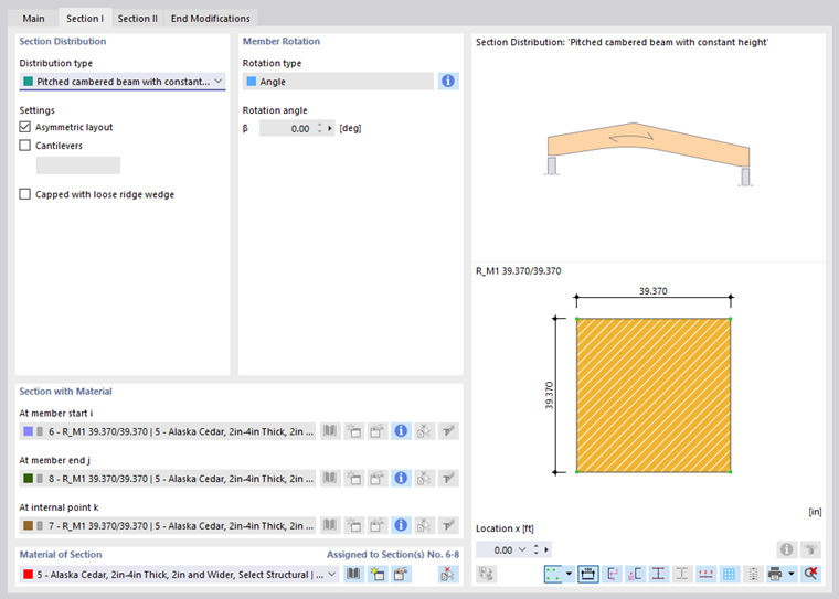
Then, in the "Section II" tab, define the beam-specific parameters, such as dimensions, inclination angle, radius of curvature, or grain orientation.
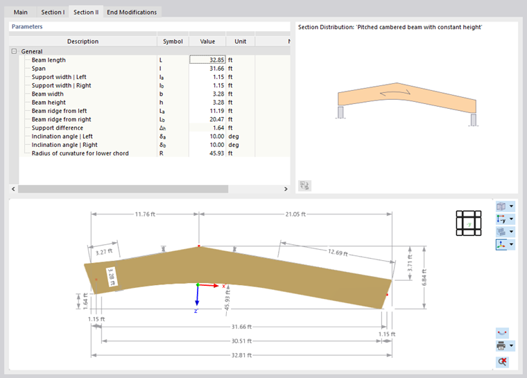
The graphic in the lower dialog section shows the individual parameter specifications. The value of the selected table row is highlighted in color.
Section with Material
In this dialog section, you can assign a cross-section to the member. It defines the stiffness of the member. You can select the cross-section in the list or redefine it using the
![]() and
and
![]() buttons (see the chapter Cross-Sections).
buttons (see the chapter Cross-Sections).
For a uniform section distribution, only the "As member start" option is possible for the member end and the internal point. For non-uniform distributions, however, you can select the cross-sections "At member end j" and "At internal point k" in the list in accordance with the system sketch (see the image Defining Member with Tapered Cross-Section on both Sides).
Material of Section
In addition to the cross-section, the material is essential for the stiffness of the member. You can select the material in the list or redefine it using the
![]() and
and
![]() buttons (see the chapter Materials).
buttons (see the chapter Materials).
Member Rotation
The member-related xyz coordinate system is defined as rectangular and oriented clockwise (see the image Member with Offset). The local axis x represents the centroidal axis of the member. It connects the start node with the end node of the line (positive direction). The member axes y and z (or u and v for unsymmetric cross-sections) represent the principal axes of the member.
The position of the local axes y and z is defined as follows: The y-axis is aligned perpendicular to the longitudinal axis x and parallel to the global XY-plane. The position of the z-axis results from the right-hand rule. The z' component of the z-axis always points "downwards" (in the direction of gravity) – regardless of whether the global Z-axis is oriented upwards or downwards. If the member has a vertical position, the local axis y is aligned parallel to the global Y-axis and the z-axis is determined according to the right-hand rule.
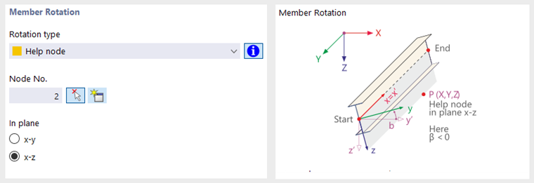
You can use various options in the list to rotate a member.
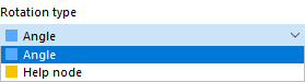
- Angle: A positive angle β rotates the axes y and z clockwise about the longitudinal axis x.
- Help node: Define the reference node and specify the member axis (y or z) that is to be aligned with this node. The help node must not lie on the straight line that is defined by the member axis x.