


A result combination (RC) superimposes the results of load cases according to certain combination criteria. The results of load cases, load combinations, and result combinations can be combined. Result combinations are primarily used for dynamic analyses.
The "Result Combinations" tab is available if
- The Result Combinations check box is activated, or
- A combination wizard is used to generate result combinations.
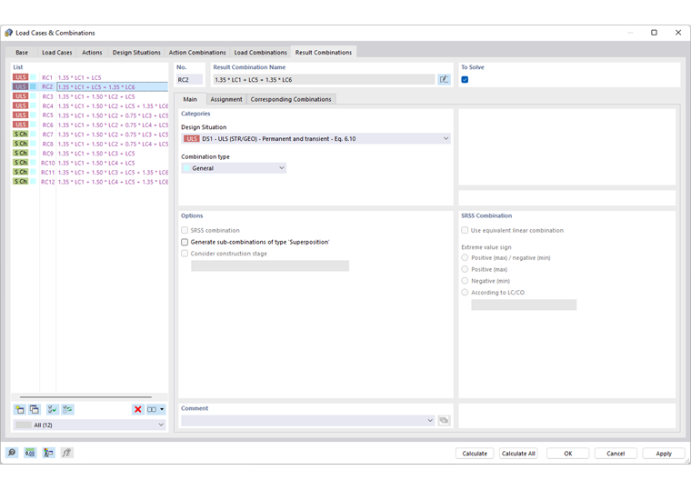
When activating the tab, the result combinations are generated according to the standard's combination rules. They are listed by design situations. If you have deactivated the Combination Wizard in the Base tab, you have to create the result combinations manually (see the section Defining Result Combination Manually).
The "Result Combination Name" is a short description. It is based on the safety factors and numbers of the load cases, reflecting the combination rules.
The "To Solve" check box controls whether the selected result combination is analyzed during the calculation.
Main
The Main tab manages the general specifications of the result combination selected in the 'List' to the left.
Categories
The "Design Situation" describes the normative specifications according to which the load cases are combined (see the chapter Design Situations).
The "Combination type" controls the criteria for superimposing the results. If the combination wizard has been used, the "General" entry appears here. For a user-defined result combination, the following options are available in the list:
- General: The linking criteria can be defined individually in the "Assignment" tab.
- Envelope – Permanent: The load cases and combinations included in the combination are always taken into account ("/p"), but are mutually exclusive ("or"). Thus, the RC represents an envelope with the most unfavorable results of all components.
- Envelope – Transient: The load cases and combinations included in the combination are considered only if they make an unfavorable contribution to the result. They are mutually exclusive ("or"). The RC represents an envelope from the results of the components. However, the signs may lead to a situation where the results of components are not included if they have no effect on the extreme values.
- Superposition: All load cases and combinations included in the combination are always taken into account ("p") and added respectively ("+"). The superposition determines the sum of all results. There are no maximum or minimum values.
Options
Usually, results are combined additively: B = A1 + A2 + A3 + … + An. If a result combination is user-defined, the "SRSS combination" check box is accessible. Thus, a superposition is carried out according to the square root of the sum of the squares method: = √(A12 + A22 + A32 + … + An2). This approach is important for modal analyses. In the SRSS Combination dialog section, you can define how the signs of extreme values are handled.
The "Generate sub-combinations of type Superposition" check box causes the components included in the result combination to be created as separate combinations. This way, you can see which combinations are used for the superposition of the results and which criteria apply in each case.
SRSS Combination
The dialog section can be accessed if the "SRSS combination" check box has been activated in the "Options" dialog section. Here, you can define how modal responses are combined and signs are handled.
The standard form of the SRSS rule combines the results quadratically according to the square root of the sum of the squares method described above. In this case, the signs get lost. Select the "Use equivalent linear combination" check box to apply the SRSS rule as an equivalent linear combination. This allows you to determine results such as corresponding internal forces and moments. Usually, they are significantly smaller than calculated according to the standard form of the SRSS rule. Results calculated according to the equivalent linear combination are consistent and the corresponding signs are correct with regard to the governing internal force or moment.
With the "Extreme value sign" options, you can control which extreme values of the load cases are included in the superposition and whether the signs should be kept. This way, the extreme values of the modal internal forces and deformations as well as the results belonging to the leading component are determined with the correct signs.
Assignment
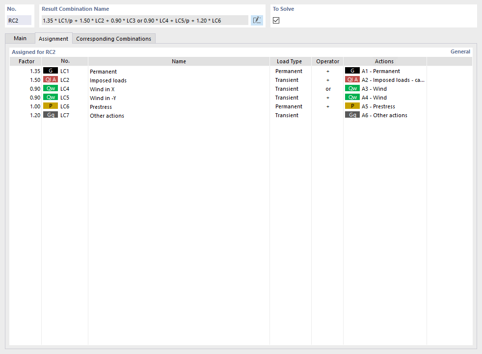
In the Assignment tab, you can check the load cases or load combinations that are included in the selected result combination and according to which criteria they are combined.
Assigned for RC
The table lists the load cases of the result combination. The values given in the "Factor" column are based on the partial safety factors and combination coefficients according to the standard. They are applied depending on the design situation and action category.
The "Load Type" describes how each load case is considered in the superposition:
- Permanent: The loading is effective in any case.
- Transient: The loading is only taken into account if the results lead to an increase of the internal forces and deformations.
The "Operator" shows the way load cases are linked:
- +: The symbol indicates an additive combination. The load case is considered independently of any other load case as soon as the results have an unfavorable impact.
- or: The criterion describes an alternative combination. The results of certain load cases are mutually exclusive, such as wind. Only the values of the loading making the most unfavorable contribution are taken into account.
Auxiliary Combinations
If the Auxiliary Combinations option is activated in the Combination Wizard dialog box for result combinations, a result combination is generated separately for each action. The result combinations are then generated from these predefined result combinations in accordance with the action combinations.
Example
The model contains the following actions with the corresponding load cases:
| A1 | Permanent |
| A2 | Live loads |
| A3 | Snow |
| A4 | Wind |
According to EN 1990, three action combinations result for the ultimate limit state:
| AC1 | 1.35 * A1/p + 1.50 * A2/p + 0.75 * A3 + 0.90 * A4 |
| AC2 | 1.35 * A1/p + 1.05 * A2 + 1.50 * A3/p + 0.90 * A4 |
| AC3 | 1.35 * A1/p + 1.05 * A2 + 0.75 * A3 + 1.50 * A4/p |
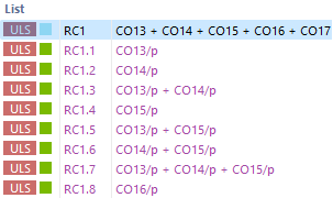
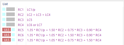
Without auxiliary combinations, the load wizard generates the following result combinations:

With the “Auxiliary Combinations” option, the load cases are first combined according to actions and then superimposed.
Defining Result Combination Manually
Use the
 button at the bottom of the 'List' to add a result combination manually. The "Assignment" tab will be adjusted accordingly. You will also find this scheme if you use the Combination Wizard for load combinations when "Result Combinations" in the "Base" tab is activated.
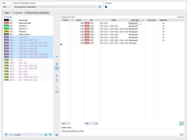
The "To Assign" column lists all available load cases, load combinations, and result combinations. To transfer an entry to the "Assigned for RC" list, use the following options:
- Double-click the entry.
- Select the entry or several entries by holding down the Ctrl key. Then, click the
 button.
The
 and
and
 buttons control the Operator that is used when linking the entries:
- +: The load cases are added.
- OR: The load cases act alternatively.
To change the "Factor" of a load case or a combination, activate the first column of the relevant row. Enter the correct factor or select it from the list.
You can adjust the "Load Type" and the "Operator" in the same way: Activate the field and select the appropriate entry from the list.
The "Syntax input" dialog section allows you to define the result combination directly. Enter the load cases or combinations with a factor, a load type symbol ("/p" or without), and an operator ("+" or "or"). Then, assign the definition criterion with the
 button.
Corresponding Combinations
In the Associated combinations tab, you can define the “related” combinations that result from the same load cases for the individual design situations.
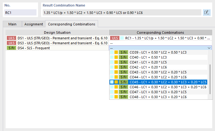
The principle is described in more detail in the chapter Load Combinations.