


This load wizard helps you apply any straight line load proportionally to members. For example, this means that you do not need to determine the member loads manually for a beam grillage.

Base
The Base tab manages the load parameters.
Generate in load case
Select the load case in the list to which the loads are to be assigned. Use the
![]() button to create a new load case.
button to create a new load case.
Categories
Load distribution
The list provides various options for how the straight-line load acts:
- Uniform: A load with constant magnitude is applied.
- Linear: The load is distributed with linear variation. In the 'Line load parameters' section, you can specify two reference nodes with the respective load magnitudes.
Coordinate system
The line load can act perpendicular to the load plane ('local z') or with reference to the global XYZ coordinate system. Alternatively, you can select or create a user-defined coordinate system.
Load direction
If the line load does not act perpendicular to the load plane, but in the direction of a global axis, the list provides various selection options.
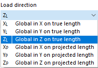
The line load can be based on the actual length (as a gravity load) or the projected length (as a snow load). The load direction is illustrated in the dialog graphic.
Line load parameters
Enter the magnitude of the uniform line load. If the load is linearly varying, you can specify the numbers of two nodes with the assigned loads here. The
![]() button can also be used to select the nodes graphically in the work window. If no suitable node exists yet for assigning the load, you can create one with the
button can also be used to select the nodes graphically in the work window. If no suitable node exists yet for assigning the load, you can create one with the
![]() button.
button.
Options
If you check the 'Ignore new members' box, the line load only acts on the currently existing members within the range of the line defined by the two nodes in the 'Line load parameters' section. Members that you add later in this range will not receive any portions of the line load.
The 'Consider member eccentricity' option controls whether the line load acts on the members in the plane without taking eccentricities into account (default). If you activate the check box, the line load is not applied to members that are offset from the plane.
With the 'Consider cross-section distribution' check box, you can control whether the line load also acts on inclined members resulting from a haunch definition (default). If you activate the check box, the line load is not applied to members in the load plane that have a non-uniform cross-section variation (see Chapter cross-section ).
Excluded Members
In the Excluded Members tab, you can define that members such as bracings do not receive proportional loads.
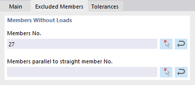
Select the members graphically using the
![]() button either individually or via a pattern member 'parallel' to all load-free members.
button either individually or via a pattern member 'parallel' to all load-free members.
Tolerances
In the Tolerances tab, you can influence the criteria according to which members and nodes are assessed as belonging to one plane or line. The parameters are described in Chapter Member Loads from Surface Loads .