


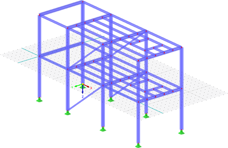
A spatially defined model can only be displayed in two dimensions on the screen. Defining objects graphically is therefore a problem, because it need to be organized in which plane they are created when clicking into the work window. The work plane controls the coordinate that is always "fixed".
The axes of coordinates of the current work plane are displayed as two green, orthogonal lines. The intersection of these lines represents the origin (zero point) of the work plane.
Work Plane
A work plane is usually parallel to one of the global planes XY, YZ, or XZ, which are defined by two axes of the global coordinate system. However, you can also arrange the work plane as a plane in any inclination or align it with a member axis by using an appropriate coordinate system.
Use the buttons in the toolbar to access various functions for setting the work plane.
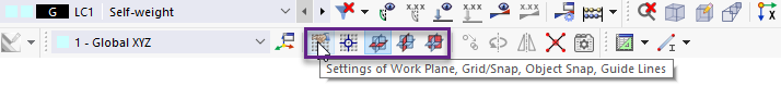
The buttons have the following meaning:
| Button | Function |
|---|---|
|
|
Open the Work Plane and Grid/Snap dialog box |
|
|
Enable a graphical selection of the work plane origin |
|
|
Set a work plane parallel to the XY-plane |
|
|
Set a work plane parallel to the YZ-plane |
|
|
Set a work plane parallel to the XZ-plane |
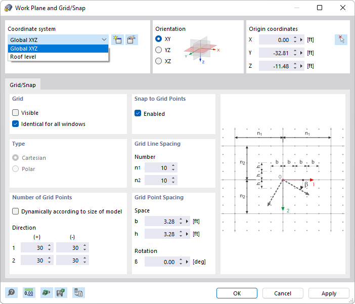
Define the "Coordinate system" which the work plane refers to. You can select a user-defined coordinate system in the list or create a new one using the
![]() button.
button.
The "Orientation" describes the position of the work plane. You can arrange it parallel to a global plane or parallel to the axes of a user-defined coordinate system (see the image UVW-Coordinate System in Roof Plane ).
The "Origin coordinates" describe the position of the work plane's zero point. You can adjust the coordinates or the point using the
![]() button.
button.
Grid/Snap
The grid consists of points displayed in the work plane. They facilitate the data input: When placing objects graphically, the object nodes snap to the grid points.
Grid
Use the "Visible" check box to show and hide the grid. If you want to use different grid settings in the windows, deactivate the "Identical for all windows" option.
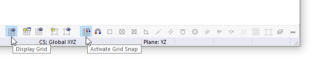
You can use the
![]() button to quickly switch the grid on and off in the CAD toolbar.
button to quickly switch the grid on and off in the CAD toolbar.
Number of Grid Points
If the "Dynamically according to size of model" check box is selected, RSTAB automatically adjusts the grid area to the dimensions of the model. Thus, there are always enough grid points available within the area of the model. After each entry, the required grid points are recalculated. For larger models, recalculating may lead to a delayed generation of graphics.
To define the number of grid points individually, deactivate the dynamic grid adjustment. Thus, separate specifications for the positive and negative "Direction" of each axis are possible. When a polar grid is set, you can specify the number of concentric grid circles.
Snap to Grid Points
The "Enabled" check box allows you to switch the snap function on and off independently of the grid display. Thus, objects can be snapped to the grid points even if the grid is hidden.
- Use the
 button to quickly switch the grid snap on and off in the CAD toolbar (see the image Buttons for Grid and Grid Snap).
- You can set the snap sensitivity in the Display Properties dialog box, under the General → Snap category. This setting also applies to the snap function for other objects.
Grid Line Spacing
The grid is structured by grid lines that are evenly spaced. Enter the "Number" of grid points after which a grid line is to be displayed. Separate specifications for Directions 1 and 2 are possible.
Grid Point Spacing
When using a Cartesian grid, you can define the "Space" of grid points separately for Directions 1 and 2. For a polar grid, specify the radial spacing R for the grid circles. The angle α describes the spacing between the grid points on the circles.
To achieve a "Rotation" of the grid in the work plane, enter the rotation angle β.