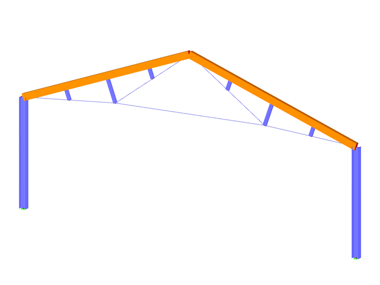
The geometry of the model is defined by members. By assigning a cross-section (that also defines the material), the member gains a stiffness.
Members can only be connected with each other on nodes. When members cross each other without sharing a common node, no connection exists. No internal forces are transferred at such crossings.
Graphically, members can be set individually or continuously. The corresponding functions can be accessed with the list button.

| Button | Function |
|---|---|

|
New single member with simple definition options |

|
New single member with advanced definition options |

|
New single member perpendicular to the work plane |

|
New single member parallel to the work plane |

|
New continuous member with simple definition options |

|
New continuous member with advanced definition options |

|
New member set |
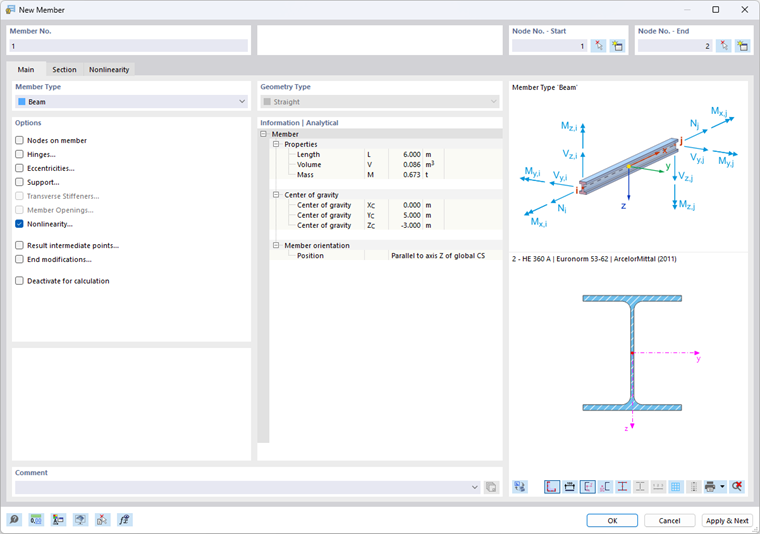
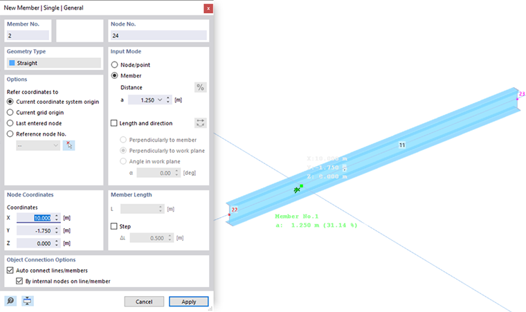
After entering a cross-section (see the image New Member), a dialog box appears that is "Simple" or "General" depending on the function. The general dialog box provides extended options, for example, to define a reference node or to apply member distances for the setting.
By default, the New Member dialog box consists of the Main and Section tabs. They are described in the following two subchapters.
Member Properties
You can view important properties of a member in the Object Properties panel:
- Select the member.
- Open the “Object Properties” panel by clicking the
 button in the toolbar.
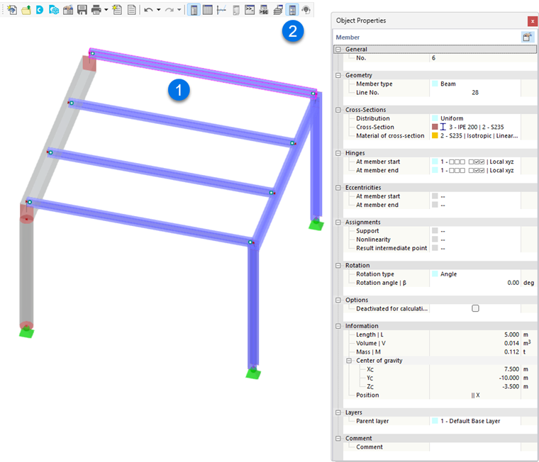
The panel shows information, such as member type, cross-section, material, and geometric data.