


The Punching tab of the "Ultimate Configurations" dialog box manages the configuration for the punching shear design checks on floor or foundation slabs. Punching shear design checks are possible for point and line loads.
The "Design Parameters" are divided into several categories.
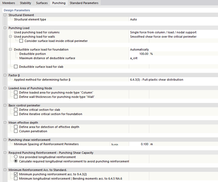
Structural Element
The program tries to recognize the structural element type automatically and to consider the relevant situation – a slab or a foundation – in the design.
You can also manually set the type in the list. This may be necessary if the algorithm does not correctly determine the boundary conditions in the model due to a special constellation.
Punching Load
This category contains several sub-items with the important parameters to determine the punching load.
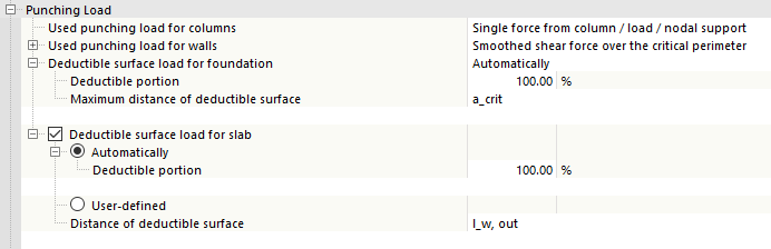
Used Punching Load for Columns
The punching load for punching shear on columns is derived directly from the column axial forces by default. As an alternative, you can switch to the application of shear forces over the critical perimeter.
You can select between the smoothed and the unsmoothed distribution of shear forces. You can also optionally "consider surface load inside critical perimeter" in order to determine the missing load component between the critical perimeter and the location of load introduction for the punching load VEd.
Used Punching Load for Walls
This setting affects the punching design for wall corners and wall ends. To determine the punching load, the smoothed distribution of the shear forces over the critical perimeter is used by default. As an alternative, you can switch to the unsmoothed distribution of the shear forces.
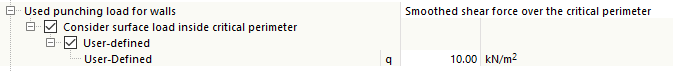
The program tries to automatically determine the surface load on a surface from the load distribution. Use the "Consider surface load inside critical perimeter" to manually specify the missing load component between the critical perimeter and the location of the load application for the punching load VEd. For this, select the "User-defined" option and then enter the surface load in the text box.
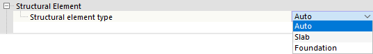
Deductible Surface Load for Foundation
In this category, you can control how the program should handle the favorable surface load within the critical perimeter on columns when designing foundation slabs. If you perform the design on the individual columns, the column axial force is used as a punching load, as described above. The load component from the favorable soil pressure within the critical perimeter can be deducted from this punching load. This surface load is generally determined "automatically" from the load distribution on a surface. Optionally, the value can be "User-defined".
The "deductible portion" of the surface load, which is subtracted from the punching load VEd, is set to 100% by default: It is assumed that the position of the critical perimeter is determined iteratively for the design of foundation or floor slabs. If you define the position of the critical perimeter as required (for example, 1.0*d), you can change the deductible portion to 50%.
The critical perimeter acrit is preset as the "maximum distance of deductible surface". In this way, the iteratively determined position of the critical perimeter is applied. As an alternative, you can switch to the "k * d" option in the list. This means that the multiple ("k"') static height ("d") is used as the position of the critical perimeter for the deductible surface load. The default setting is "1.0 * d"; adjust the factor k, if necessary.
Deductible Surface Load for Slab
This category corresponds to the options described in Section Deductible Surface Load for Foundation. This allows you to reduce the punching load for the structural components of the "plate" type, if there are favorable surface loads. The function is deactivated by default.
Factor β
Ba default, the load increasing factor β is determined using the formulas in Section "6.4.3(3) – Full-plastic shear distribution". However, there are also alternatives to select from in the list.
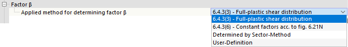
- "6.4.3(6) – Constant factors acc. to fig. 6.21N": The program applies constant approximate values to the individual nodes, depending on the determined geometry (a corner, edge, center, wall end, or wall corner).
- "Determined by Sector-Method": This method is described in the technical article Determining Load Increasing Factor β with a Sector Model for RF‑PUNCH Pro, which also applies to RFEM 6.
- "User-Definition": You can set the load increasing factor β manually.
Loaded Area of Punching Node
The geometry of the punching point—for example, the dimensions of a connected column—is generally determined directly from the cross-section of the column. If you want to use a different dimension for the design, activate this option. Separate specifications are possible for the "Column" and "Wall" punching node types.
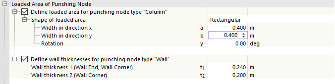
Define the geometry of the loaded area manually. This overwrites the dimensions determined from the topology for all nodes with this configuration assigned.
You can also use this function to design a nodal load or a line load that has no dimensions by the concept.
When entering the "wall thickness", make sure that the thickness t1 is always assigned to the line with the smaller numbering in the model. The wall thickness t2 is assigned to the line with the higher line number.
Basic Control Perimeter
In this category, you have the option to manually specify the critical perimeter for the design of a slab or a foundation (floor slab).
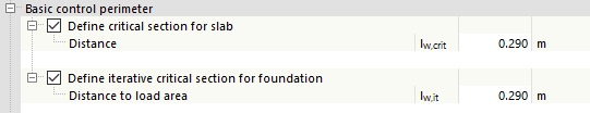
No manual entry is generally required, as the program automatically determines the critical perimeter. The text boxes are, therefore, only accessible after activating the function.
Mean Effective Depth
The static height d is generally determined at the location of the connected node. For surfaces with a variable surface thickness, however, it may be necessary to adjust the "area for detection of effective depth". You can then adjust the "distance from loading area" in order to apply the lower effective depth, if necessary.
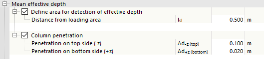
For example, to consider the column penetration of a reinforced concrete column into a reinforced concrete slab, you can define the "column penetration". The calculated effective depth d is then reduced by the specified values Δd during the calculation.
Punching Shear Reinforcement
In this category, you can define the "minimum spacing of reinforcement perimeters" sr,min, which is used when determining the required punching shear reinforcement. A minimum distance of 10 cm is set by default.
Required Punching Reinforcement – Punching Shear Capacity
There are two options for determining the punching shear capacity:
- "Use provided longitudinal reinforcement": The program applies the provided longitudinal reinforcement that was entered for the surface at a node of punching shear.
- "Calculate required longitudinal reinforcement to avoid punching reinforcement": The program automatically increases the longitudinal reinforcement in order to avoid the need for punching reinforcement.
Minimum Reinforcement Acc. to Standard
If a punching reinforcement is required, the "minimum punching reinforcement acc. to 9.4.3(2)" is taken into account by default. However, as long as the load-bearing capacity VRd, c is not exceeded by VEd, this setting has no effect on the design of the node.
In the case of design according to DIN EN 1992‑1‑1, you can activate the "bending moments acc. to 6.4.5 NA.6". In this way, a minimum bending moment is determined from the punching load VEd, for which the required longitudinal reinforcement is calculated. The result is integrated in the "Navigator – Results" in the display of the required longitudinal reinforcement.
Dlubal_KohlA.png?mw=760&hash=a34ae1946973815cfe0b3a1c91d699805837db4f)