


Set the design results of the reinforcement cross-sections to be graphically displayed on the surfaces in the 'Navigator - Results'. The specific results for the required reinforcement, the existing reinforcement, and the uncovered reinforcement are available for selection.

For each surface point, the cross-sectional area of the selected reinforcement type is displayed.
Upper and lower layer
The upper and lower reinforcement are applied according to the assignment you have defined for each surface reinforcement type.
You can show and hide the surface axes via the Show/Hide Local Coordinate Systems of Surfaces entry in the surface context menu. Alternatively, use the 'Navigator - Display' (Model → Base Objects → Surfaces → Surface Coordinate Systems x, y, z).
Reinforcement direction
You assigned reinforcement directions 1 and 2 of the reinforcement directions to the surfaces in the concrete design properties. You can control the display of the current reinforcement direction with the Reinforcement Direction check box in the 'Navigator - Results'.

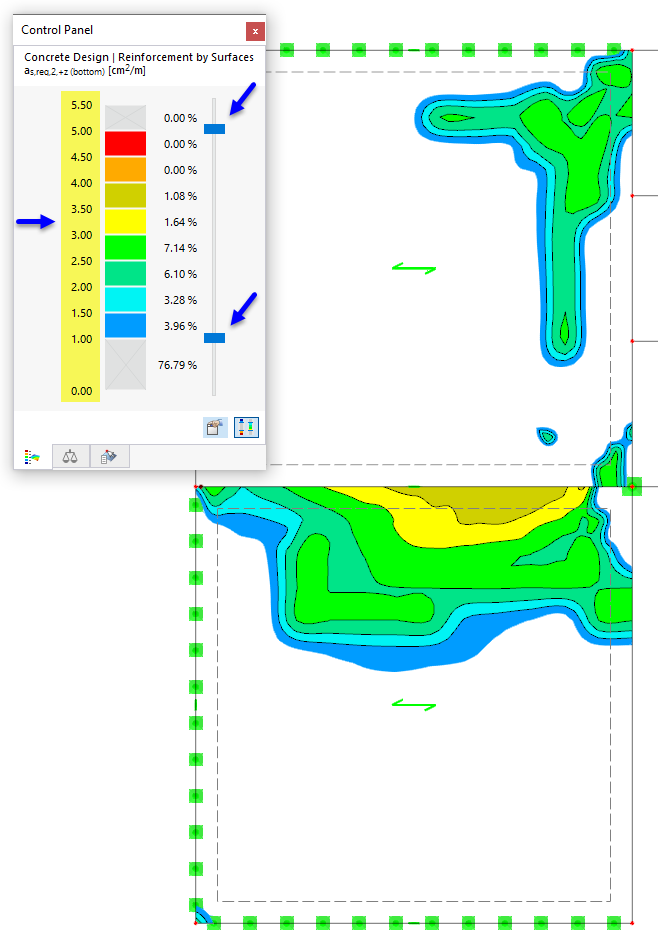
Control panel
The color assignments of the reinforcement cross-sections are specified in the control panel. If necessary, you can adjust the colors there, hide color ranges, and define objects for result display (see chapter control panel of the RFEM manual).
Reinforcement notation set
You can replace the reinforcement specifications of the values in [cm²/m] or [in²/ft]) in the control panel with a description of the reinforcement, for example based on bar diameter and bar spacing.
You can open the 'Edit Result Panel' dialog either with the 'Edit Result Panel' button
![]() or by double-clicking the result panel ➀.
In the 'Edit Result Colors' dialog, activate the Custom Value Set option ➁. Check the Reinforcement Designation option ➂. You have the option to change the number of ranges to be covered using the 'create new set' function in the 'Current Color Palette' dialog box ➃. Then use the
or by double-clicking the result panel ➀.
In the 'Edit Result Colors' dialog, activate the Custom Value Set option ➁. Check the Reinforcement Designation option ➂. You have the option to change the number of ranges to be covered using the 'create new set' function in the 'Current Color Palette' dialog box ➃. Then use the
![]() button in the 'Reinforcement Notation Set' section to open the 'Edit Reinforcement Notation Set' dialog ➄.
button in the 'Reinforcement Notation Set' section to open the 'Edit Reinforcement Notation Set' dialog ➄.

In the dialog, first define the basic execution of the surface reinforcement. Three variants are available in the 'Reinforcement designation type' list ➅:
- Reinforcing bars
- Reinforcing bars and additional reinforcing bars
- Mat and additional reinforcing bars

The required basic coverage of the surface reinforcement can be provided either by bar reinforcement or by reinforcement meshes. If you select the 'Mat' option, you can define the suitable mat in the 'Base reinforcement mat' section.
For areas with increased flexural tension demand, it is possible to display additional required reinforcement in the form of reinforcing bars ➆. The relevant areas can be selected via a color gradation. In the 'Current Color Palette' section of the 'Edit Result Colors' dialog (see ➃ in the image Application of the reinforcement designation set), you can define how many different reinforcement areas are to be considered.
The areas covered by the base reinforcement and the additional reinforcing bars are visualized accordingly via iso-surfaces or iso-lines after 'OK'.
The
![]() button can be used to automatically sort the additional reinforcing bars according to the effective reinforcement area ➇.
button can be used to automatically sort the additional reinforcing bars according to the effective reinforcement area ➇.

You now have the option of saving the created reinforcement designation set across positions using templates for future projects ➈.
Values on surfaces
The 'Values on Surfaces' category at the end of the upper navigator area offers various options for displaying result values on the surfaces.

The functions are described in the chapter result values on surfaces of the RFEM manual. You can also use them to evaluate the design results.
With the Current Selection option, the values of the reinforcement type you defined above in the navigator are displayed. The result values in the grid points or FE mesh points – adjustable in the lower navigator area – thus correspond to the surface distributions (see image above).
The Groups option allows you to display the reinforcement values layer by layer. The values are plotted in the corresponding reinforcement direction. With this display type, it is recommended not to display any result distributions.

With the Specific option, you can define the result types for the reinforcement-related values yourself.

