In the Main tab of the "Serviceability Configurations" dialog box, the settings for members and surfaces are managed together.

The "Design Parameters" are divided into several categories.
Stress Analysis
In this category, you can specify which stress analysis should be performed. The analysis of the "limitation of steel stress σs" is activated by default.
Crack Width Analysis
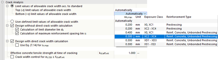
This category manages the settings for the crack width analysis. The "limit values of allowable crack width acc. to standard" are preset. They are determined "automatically" from the exposure class type assigned to the structural component. As an alternative, you can specify the value wk,max directly in the list.
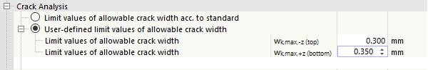
"User-defined limit values of allowable crack width" are also possible. Activate the check box, then specify the limit values for the top and bottom sides of the surfaces and members.
Crack widths outside the range of 0.20 mm to 0.40 mm can only be specified if the "Design with direct crack width calculation" option is active. With the indirect crack width calculation via the limit diameter or limit distance, the design is only possible for crack widths of the range from 0.20 mm to 0.40 mm. So if you want to design a limit value of the crack width < 0.20 mm, deactivate “Design without direct crack width calculation” check box first.
The "Design without direct crack width calculation" check box allows you to determine whether the design is carried out according to EN 1992‑1‑1, 7.3.3, by calculating the limit diameter lim ds and/or the maximum reinforcement spacing lim sl.
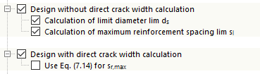
It is also possible to perform the "design with direct crack width calculation" according to EN 1992‑1‑1, 7.3.4.
The "Effective concrete tensile strength at time of cracking" option allows you to specify a factor kct,eff,wk, which is used to multiply the concrete tensile strength fctm for the crack width calculation.

Furthermore, you can activate the crack width control for the finite elements and member locations with the concrete stress σc,I,Ed ≤ fct,eff,wk.
As,min for Effects Due to Restraint
As a rule, a load due to constraint (for example, from the dissipation of the heat of hydration) is not directly represented as a load in the RFEM model. Nevertheless, the add-on can perform design for such situations and carry out a "calculation of minimum reinforcement area As,min", which is necessary because of the effects due to restraint.
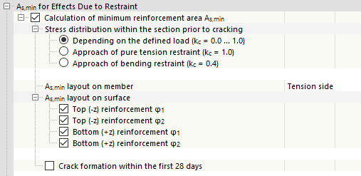
In the "Stress distribution within the section prior to cracking" category, there are three options for the selection.
- "Depending on the defined load": As an input value for the calculation of the minimum reinforcement As,min, the program requires, among other things, the stress distribution within the cross-section before the initial cracking. Using this option, the program analyzes the stress distribution from the existing load combinations of the design situations for serviceability, and then determines the coefficient kc by element or x-location. Thus, the coefficient kc can vary between 0.0 and 1.0.
- "Approach of pure tension restraint": If there is pure tensile load, the coefficient kc = 1.0 is applied to the entire structural component.
- "Approach of bending restraint": If there is bending or bending with axial force, the coefficient kc = 0.4 is applied for the entire structural component.
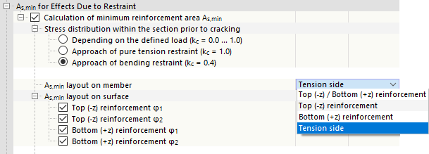
The options of an "As,min layout on member" depend on how the above-described determination of the stress within the tension zone is carried out before the initial cracking. Using the standard setting "Depending on the defined load", the "Tension side" option is only available, since the program determines the tension side from the load and only applies the minimum longitudinal reinforcement there. Using the "approach of pure tension restraint", the minimum reinforcement is distributed uniformly to the "Top (-z) / Bottom (+z) reinforcement" on both sides of the member. If activating the "approach on bending restraint", there are various options of arranging the minimum reinforcement in the cross-section.
For the "As,min layout on surface", you can individually specify on which side of the surface should be the minimum reinforcement caused by the effects due to restraint. By default, all four reinforcement directions are activated (see the image above). However, you can also apply the minimum reinforcement for a certain position or direction only.
If you check the "Crack formation within the first 28 days" check box, you can adjust the concrete tensile strength at the time of the first cracking by using the factor fct,eff,As,min.
Further theoretical background on this topic can be found in the technical article Assumptions for Effective Tensile Strength Connected with Determining Minimum Reinforcement According to DIN EN 1992‑1‑1 7.3.2.
In the case of design according to DIN EN 1992‑1‑1, the "0.85*As,min for slowly hardening concrete" option is available. It allows you to reduce the determined minimum reinforcement area by 15%.
For DIN EN 1992‑1‑1, it is also possible to specify a "Type of Restraint". You can use the options in the list to determine whether there is an internal or external action due to restraint.
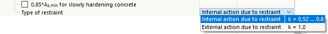
This specification controls the factor "k", which is included in the determination of the minimum reinforcement, and thus the required reinforcement amount.
Deflection Analysis
The add-on follows a "design concept" for the analysis: If you select the "Limitation of deflection" check box, the program checks the structural components with regard to allowable limit values and gives the corresponding design criterion. The support conditions of the structural components play a governing role.

In the "limit values of allowable deflection" category, the limit value for the design with the quasi-permanent design situation is L/250 for a "support on both sides" and Lc/100 for a "quasi-permanent support" by default.
If you select the "Consider resistance of concrete between cracks (tension stiffening effect)" option, the stiffening effect of the concrete to tension between the cracks is taken into account in the deflection analysis. This effect is also known as "tension stiffening": In the case of cracked reinforced concrete parts, the tensile forces in the crack are absorbed by the reinforcement alone, but the tensile stresses are transferred to the concrete via the (displaceable) coupling between two cracks. Thus, the concrete contributes to the resistance of the internal tensile forces, which leads to an increased stiffness of the structural component.
In the analytical deformation calculation, the damage of the concrete cross-section in the cracked state is taken into account using the distribution coefficient ζ. This coefficient is automatically determined from the loading situation by element or x-location. If you select the "Consider minimum value of distribution factor" option, you can specify the minimum value for ζ, for example, to apply the "minimum damage" to the locations with zero moment transmission that would not result from the defined load.
Determination of Longitudinal Reinforcement
This category is available for the design according to DIN EN 1992‑1‑1.

The “Calculation of required longitudinal reinforcement for selected serviceability design situation and design checks” check box controls whether the longitudinal reinforcement should also be designed to fulfill the serviceability design checks: If the check box is selected, the program designs the reinforcement for the serviceability design by iteratively increasing the reinforcement. The required load-bearing reinforcement for the specified service load is used as the starting value. The reinforcement design ends without a result if the member spacing sl of the possible longitudinal reinforcement reaches the member diameter dsl, resulting in a non-designable situation. The reinforcement is designed for the following design checks:
- Stress analysis
- Crack width analysis
- As,min for forced stress
The reinforcement for the SLS design checks is calculated using the governing reinforcing steel stress from all selected types of design (σs, wk, lim ds, max. sL). This approach has a positive effect on the calculation time. For all non-governing design checks, the required reinforcement is specified in the design check details as a simplified relationship between the governing design steel stress and the allowable steel stress of the design check. If you need the exact reinforcement values for each type of design in the SLS, deactivate the “Required reinforcement based on minimum σSLS” check box.
Crack State Detection
In this category, you can determine whether the crack states should be analyzed using the individual load combinations or the envelope of these combinations.
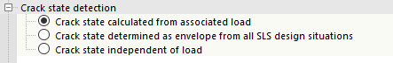
The calculation with the envelope often shortens the calculation time, but may lead to less economical results.