


In the "Design Supports & Deflection" tab, you can assign specific support conditions to the member, member set, or representatives. Design supports affect the design checks (moment redistribution, moment reduction, shear force reduction) and the reinforcement (anchorage length). Furthermore, you can enter the specifications for the deflection analysis here.

Design Support
If you have already defined a design support type in RFEM or RSTAB, you can select the corresponding entry for the "design support at member start" and the "design support at member end" in the list (see the image Defining Design Supports).
Use the
![]() button or the list entry to create a new support type in a separate dialog box (see the image New Design Support).
button or the list entry to create a new support type in a separate dialog box (see the image New Design Support).
The
![]() button allows you to edit the support type selected in the list. You can use the
button allows you to edit the support type selected in the list. You can use the
![]() button to graphically adopt the type from another member.
button to graphically adopt the type from another member.

Type
The "Concrete" type is set in the list by default. This type is linked to concrete-specific support properties, and you can define it in the "Support in z-axis" section.
Support in z-axis
The "Active" check box controls whether the support is effective in the direction of the local z-axis of the member.
There is usually a "direct support" of the beam. However, if the member transfers the load to another beam as a "joist", there is an indirect support.
Enter the "support width w". It is related to the longitudinal axis x of the member. By default, the "support depth" d results from the cross-section width of the member; it is related to the transverse axis y. If you want to specify the support depth manually, deactivate the "By section width of member" check box.
The "Monolithic Connection" option allows you to control whether there is a rigid connection to the support or a rotational support, allowing for the reduction of the support moment.
"Inner supports" have different geometry conditions than the end supports in order to determine the design moments and anchorage lengths. They are illustrated in the dialog box graphic. For an inner support, you can specify the ratio of moment redistribution δ to the elastically determined initial moment in order to consider the limited redistribution of moments for continuous structural components, for example, according to EN 1992‑1‑1, 5.5 (4).
The "Active for deflection design" check box controls whether the support properties in the direction of the local z-axis of the member are effective for the deflection analysis. If you do not want to consider the design support for the segmentation, deactivate the "Active for deflection design" option.
Support in y-axis
The "Active for deflection design" check box controls whether the support properties in the direction of the local y-axis of the member are effective for the deflection analysis.
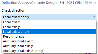
Deflection Analysis
The "check direction" specifies which deformation results are checked during the design. In the list, you can the local axes y and z, as well as the resulting displacement.
The "displacement reference" controls which model is used as a reference for the deformation analysis. The list includes two options:
- "Deformed segment ends": For the local deflection analysis, the deflection values are reduced by the deformation values of the start and end nodes. The design checks are related to the connecting line between the start and end nodes of the deformed member or member set. Generally, the deformations have to be designed relative to the displacements in the entire structural system.
- "Undeformed system": The local deformation values uy and uz are taken directly from the results and used for the design.
Using the assigned design supports, the program creates "segments" on the member or member set. The tables for the "segment in the z-axis" and "segment in the y-axis" allow you to determine the reference lengths separately for each design check direction. For each design location in a segment, the "length" Lc specified in the tables is used as the reference length for determining the limit value. If you want to change the automatically determined reference lengths, select the "User-Defined Lengths" check box and then enter your values. Please note that these lengths are not automatically adjusted if you change the member length later in the model.
The "Precamber wc" column of the tables provides you with the option to consider a user-defined value of the precamber ("rise") in the design, and thus to reduce the deflection value. The precamber is assumed to be a single-wave shape on the entire member or member set. Enter the precamber z as a positive value if it is opposite to the local member axis z. To design the resulting direction, the precamber components are converted into the resulting direction.
You can enter the limit values of the deflection in the Serviceability Configurations dialog box for bilateral supports (beams) and for one-sided supports (cantilevers). When designing a segment, the relevant limit value is taken into account according to the assigned design support: A segment with design supports on both sides or with no design supports is regarded as a beam; a segment with a design support on one side is a cantilever.
Graphic
You can see the member section on the right, and the longitudinal section below. The design supports used for the design checks are also shown there. The functions of both graphic areas are described in Chapter Shear Reinforcement .