


The "Punching Reinforcements" allow you to define how to carry out the reinforcement against punching in a surface. The parameters of perimeters and legs, like the surface reinforcements, are types that you can then assign to the corresponding nodes. The options for reinforcement layout comply with the design standard.
Input Options
The program provides several options for entering punching reinforcements.
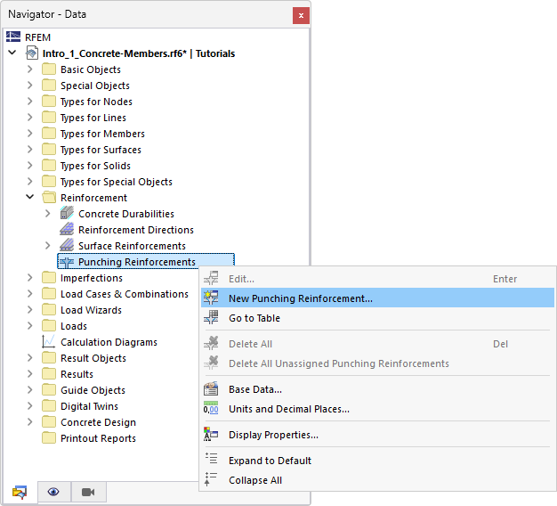
Shortcut Menu of Navigator
In the "Navigator – Data", right-click the Punching Reinforcements entry in the Reinforcement category. Then, select New Punching Reinforcement from the shortcut menu.
Table
In the table, set the Structure main category and the Reinforcement subcategory. Double-click an empty row in the Punching Reinforcements worksheet.

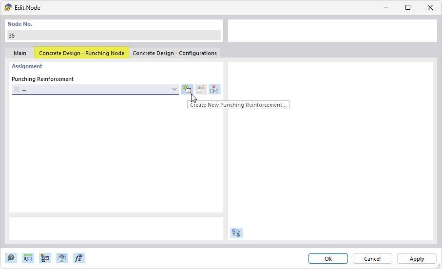
Node Property
You can create a new punching reinforcement directly as a property of a node. Open the Edit Node dialog box. In the "Design Properties" section, select the Punching Design check box, and then switch to the Concrete Design – Punching Node tab.
Main
In the Main tab, you can define the main specifications of a punching reinforcement.

Parameters
Material
Assign material to the punching reinforcement. If you have already defined a suitable reinforcement steel in the model, you can select it in the list. Otherwise, you can use the
![]() button to create a new material by opening the New Material dialog box, where you can access the material library. You can also access this library directly by using the
button to create a new material by opening the New Material dialog box, where you can access the material library. You can also access this library directly by using the
![]() button. The "Reinforcing Steel" material is preset here.
button. The "Reinforcing Steel" material is preset here.
Use the
![]() button to change the material that has already been assigned. The
button to change the material that has already been assigned. The
![]() button allows you to graphically transfer the reinforcing steel from another surface.
button allows you to graphically transfer the reinforcing steel from another surface.
Rebar Diameter
Define the diameter ds of the reinforcement stirrups or headed studs. Several options are available for selection in the list. However, the diameter can also be user-defined.
Categories
Type
The type describes the geometric position of the punching reinforcement. The following options are available for design according to EN 1992:
- Vertical (reinforcement legs without a slope)
- Double-headed studs | Ribbed shaft (according to European Technical Guideline EOTA/ETA [1]), see also manufacturer-specific values for headed studs)
If the design is based on ACI 318 and CSA A23.3, the following options are selectable in the list:
- Vertical | Stirrup
- Vertical | Multiple legs
- Vertical | Crosstie
- Double-headed studs
- Headed studs with base rail
Each type is illustrated in the dialog graphic.
Distances
Define how the legs or the headed studs of the punching reinforcement are distributed in perimeters. For the design according to EN 1992, the following options are available in the list:
- Vertical
- Uniform
- Differently
- Double-headed studs
- Slabs | Uniform
- Foundation | Uniform
- General
If the design is performed according to ACI 318 or CSA A23.3, only a constant distribution is possible.
In the Placement tab, you can define the reinforcement arrangement in detail.
Placement
The type describes where the punching shear reinforcement is inserted: For the design according to EN 1992, the stirrups are arranged “radially” in the perimeter sections. If the punching shear design is performed according to ACI 318 and CSA A23.3, the reinforcement elements are placed “axially.”
Placement
In the Placement tab, you can define how the punching reinforcement is arranged. The input options are aligned with the specification in the Categories section of the "Main" tab.
Uniform (Stirrups)
In the case of a constant arrangement, the stirrups are distributed uniformly in the individual perimeters.

Define the number of perimeters np and the number of legs in each perimeter nl. Thus, an equal number of stirrups is placed in each perimeter.
The perimeter spacing can either be determined automatically as "Multiple effective depth (k * d)" or defined "Absolute" with user-defined spacing. The parameters are shown in the dialog graphic.
Differently (Stirrups) / General (Studs)
For the design according to EN 1992, you can also arrange the punching reinforcement—stirrups or headed studs—in a user-defined way.

Define the number of legs nl or the number of studs nli, as well as the spacing ksr of the perimeter in the table. Each line describes the parameters of a perimeter.
#banner@tip#If you change the perimeter distance to "Absolute" in the lower section, you can define the distances between perimeters sr by entering lengths.
Slab/Foundation | Uniform (Studs)
In the case of a uniform arrangement of the punching reinforcement in the slab or foundation, the studs are distributed at equal intervals throughout each perimeter section.

Specify the number of perimeter sections np and the number of studs nl in each perimeter section. This ensures that the same number of studs is placed in each perimeter section.
The Perimeter spacing can either be determined automatically as a “multiple static depth (k * d)” or set as “absolute” with user-defined distances. The parameters are displayed in the dialog graphic.
- banner.text
Manufacturer-Specific Values for Headed Studs
The design of shear connections using double-headed studs is based on the technical guideline EOTA TR 060 [1]. Manufacturers of double-headed studs or shear rails also refer to this design standard. For CE marking, products have to be tested for technical suitability and approved with a corresponding ETA certificate.
For design in the program, you need the product-specific ETA approvals. These are typically provided by the manufacturers. The values in these approvals may vary from manufacturer to manufacturer. You should therefore verify that the parameters are correctly entered in the design configuration:
- Open the Edit Ultimate Configuration dialog box.
- Switch to the Standard Parameters tab.
- Scroll to the last category Punching shear resistance – headed studs – EOTA TR60


