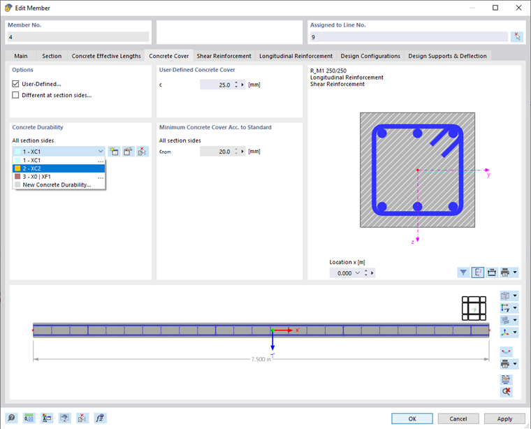
In the Concrete Cover tab, you can control the concrete cover of the reinforcement that is used for the member design.
Options
Two check boxes in this section are deactivated by default, so the concrete cover is determined using the exposure class. Select the corresponding option to specify the User-Defined concrete cover or the concrete cover Different at section sides.
Concrete Durability
In most cases, the concrete cover is controlled by the concrete durability assigned to the member. The program determines the concrete cover directly using this specification. If you have already defined the types of Concrete Durability, you can select the proper type from the list.
Use the
![]() button to create a new (or further) type. The
button to create a new (or further) type. The
![]() button allows you to edit the concrete durability type selected in the list. You can use the
button allows you to edit the concrete durability type selected in the list. You can use the
![]() button to graphically adopt the type from another member.
button to graphically adopt the type from another member.
Minimum Concrete Cover Acc. to Standard
Here, you can specify the minimum concrete cover cnom that, according to the Standard , must be observed for the selected exposure class. This value cannot be changed.
User-Defined Concrete Cover
This section is only displayed if you have selected the User-Defined check box in the options Options section. You can specify the concrete cover manually here (see the image Defining Concrete Cover). The value c is the distance between the stirrup outside and the edge of the cross-section.
Different Concrete Cover at Section Sides
If there is no uniform exposure class for the cross-section, you can also specify the concrete cover for the individual sides. To do this, select the Different at section sides check box in the Options section. You can then select the proper exposure class for each side of the cross-section (top, bottom, left, right) in the "Concrete Durability" section and thus control the concrete cover.
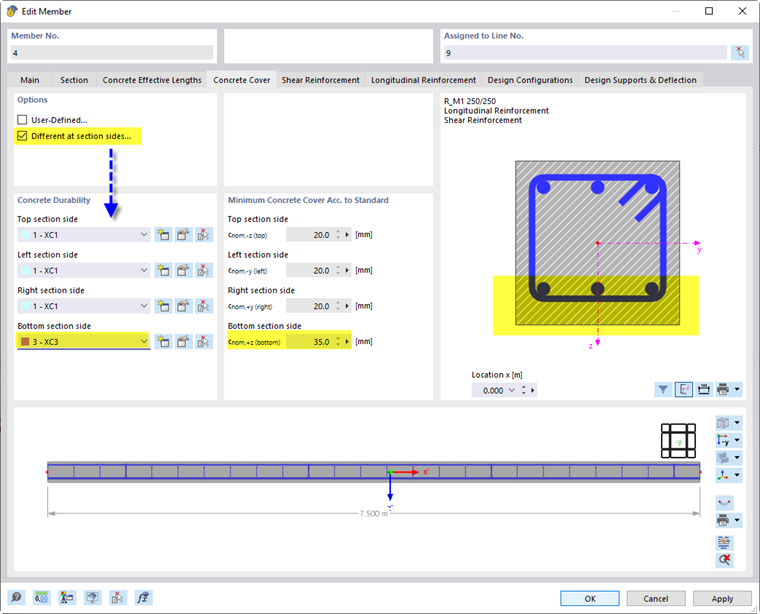
Graphic
You can see the member cross-section on the right, and the longitudinal section below. The functions of both graphic areas are described in Chapter Shear Reinforcement .