In the Longitudinal Reinforcement tab, you can define the reinforcement to be used for the bending and axial force design of the member.

Positions
This section provides the option to define reinforcement positions for the longitudinal reinforcement. Only one position is preset here, representing a type of "basic reinforcement". You can adjust this preset and also add further positions (see image Defining longitudinal reinforcement), for example, to arrange reinforcement with additional bars in sections. Use the
![]() button at the end of the list to create new positions. With the
button at the end of the list to create new positions. With the
![]() button, you can also copy the selected position and then adjust the copy.
button, you can also copy the selected position and then adjust the copy.
For ribs, you have the option to generate the longitudinal reinforcement in the chord from the surface reinforcement. To do this, click the
![]() button at the end of the list. The program then generates the longitudinal reinforcement of the rib member from the surface reinforcement that exists in the connected surface. These positions are displayed in the list but cannot be modified. With the
button at the end of the list. The program then generates the longitudinal reinforcement of the rib member from the surface reinforcement that exists in the connected surface. These positions are displayed in the list but cannot be modified. With the
![]() button, you can also deactivate the surface reinforcement.
button, you can also deactivate the surface reinforcement.
Parameters
In this section, you can specify the properties of the longitudinal reinforcement. The parameters always refer to the position selected in the 'Positions' list.
Basic Data
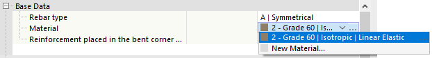
Select the 'Reinforcing bar type' in the list. Various options are available for arranging the reinforcement.
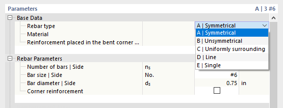
The options result in the following distribution scheme:
| Reinforcing bar type | Arrangement |
|---|---|
| Top and bottom identical | |
| Top and bottom different, side reinforcement optional | |
| Equal on all sides (for columns) | |
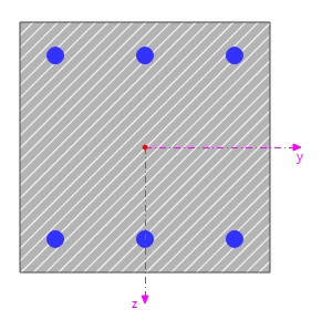
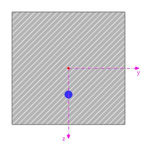
| Symmetrical in one layer (for additional bars) | |
| Single bar (for additional bar) |

The inputs in the Reinforcement Parameters category are adapted to the reinforcing bar type.
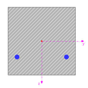
A "basic reinforcement" is preset. It is arranged 'Symmetrically' with three reinforcing bars of 20 mm each on the top and bottom sides. This reinforcement serves to enable design even without a specific reinforcement definition. However, you usually need to adjust the reinforcement so that the verifications correspond to the real conditions! Otherwise, the program would use the presented basic reinforcement for all verifications.
If you do not adjust the reinforcement and initially want to keep the basic reinforcement, you should evaluate the 'Distribution of required or uncovered reinforcement' after the design. Note that the distribution of required or uncovered reinforcement only considers the ultimate limit state! The verifications for the serviceability limit state and fire resistance necessarily require the reinforcement to be defined as close to reality as possible.
Assign a Material to the longitudinal reinforcement. If you have already defined the appropriate reinforcing steel in the model, it is available for selection in the list.
You can also create a new material via the
![]() button in the input field by accessing the material library in the
New Material
dialog.
button in the input field by accessing the material library in the
New Material
dialog.
With the 'Reinforcement placed in bent corner of stirrup' check box, you can control whether the reinforcing bars are arranged at the top or bottom stirrup edge or exactly in the radius or the center of the bent corner.

This option is particularly interesting for columns. For beams, however, which are mainly loaded with a moment about the y-axis of the member, the reinforcement can be arranged at the top or bottom stirrup edge.
Reinforcement Parameters
The input options in this category are adapted to the Reinforcing bar type.
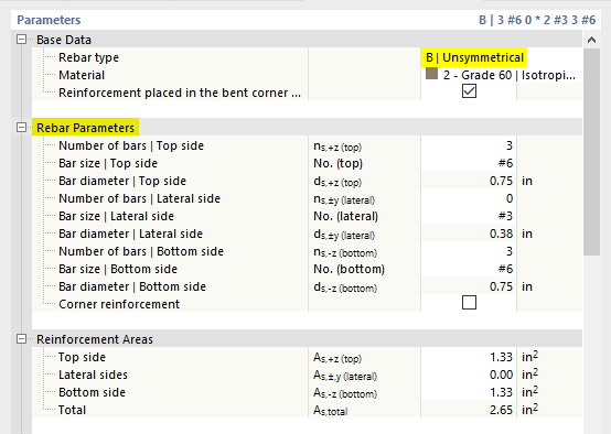
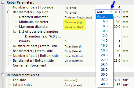
Specify the 'Number of bars' ns and the 'Rebar diameter' ds of the longitudinal reinforcement. If the program is to determine the number or the diameter during the design, select the Auto option.
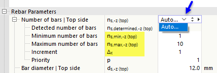
If the number of bars is to be determined, you can specify the minimum and maximum allowable number as well as the increment Δx during the design process. With the priority, you can control for multi-layer reinforcements whether a second layer should only be activated when needed. Reinforcements with the value 1 have the highest priority.
If the program is to determine the rebar diameter, you can specify the smallest and largest possible diameter for the design.
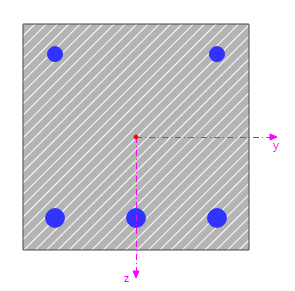
For the reinforcing bar types 'Line' and 'Single', you can also define the offset of the reinforcing bars. This value can be referenced to the stirrup, the concrete cover, or the cross-section edges (see also the Additional Reinforcing Offset category). The graphic provides a good control option here.

Reinforcement Areas
In this category, you obtain information about the cross-sectional areas of the placed reinforcement (see image Reinforcement parameters). This information is helpful if, after an initial calculation, you find that individual verifications are not met with the existing reinforcement. You can then check the distribution of required or uncovered reinforcement, compare it with the information in this dialog, and then adjust the diameter or the number of bars accordingly.
Field Location
In this category, you specify where the 'Field' with the longitudinal reinforcement is arranged in the member. You can define this location with a 'Reference' to the start, the end, or an x-location. Select the corresponding option in the list to set the reference point for the field location.

With a 'Field', you have the option to arrange additional reinforcement in a member section and thus provide locally uncovered required longitudinal reinforcement.
For a reference to the 'Start' of the current member, enter the field distances with positive signs; for a reference to the 'End' of the member, enter them with negative signs.
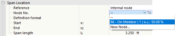
If the member is divided by a node of the 'On Member' type (which does not separate the member, unlike a standard node), you can also define the field referenced to this internal node.
Furthermore, you can control with the 'Definition format' whether the distances are to be specified absolutely in length or relatively in percentage.
Specify the 'Start' x1 and the 'End' x2 of the field. The 'Span' ls of the field thus represents the length of the longitudinal reinforcement in the member.
If the program is to adapt the length of the reinforcing bars to the statically required reinforcement areas, select the Auto option. This enables an economical design of the reinforcing bar.
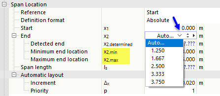
For the automatic determination, the field area must be roughly defined: Specify the minimum and maximum start or end location.
Additional Reinforcing Offset
This category is available for the reinforcing bar types 'Symmetrical', 'Unsymmetrical', and 'Uniformly surrounding'. It allows you to position the longitudinal reinforcement in the member individually.
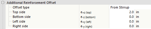
Select the 'Offset type' in the list, which regulates the reference of the distances. The following options are available:
- 'From stirrup': The distances ez and ey refer to the inner edge of the defined stirrups.
- 'From concrete cover': The offset of the longitudinal reinforcement results as the distance from the outside of the cross-section minus the concrete cover minus the distances ez and ey.
- 'From cross-section surface': The offset of the longitudinal reinforcement results as the distance from the outside of the cross-section minus the distances ez and ey.
Anchorage Start / Anchorage End
For the anchorage length verifications, information on the anchorage of the longitudinal reinforcement is required. Various options for the 'Anchorage start' and the 'Anchorage end' are available for selection in the list.
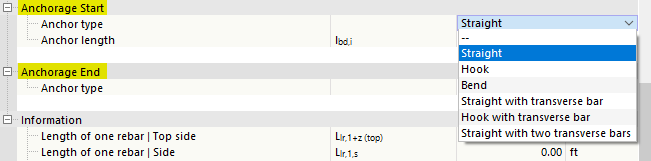
Specify the 'Anchorage length' lbd and, if necessary, the 'Bending diameter' dbr for both ends.
Information
Finally, you find the following information on the longitudinal reinforcement of the current position:
- Length of a reinforcing bar Llr,1
- Length of all reinforcing bars Llr as sum
- Weight of a reinforcing bar Wlr,1
- Weight of all reinforcing bars Wlr as sum
Graphic
On the right, you see the cross-section of the member; below, the longitudinal section. The functions of the two graphic areas are described in the Shear Reinforcement chapter.