


In the result tables of the "Concrete Design" category, you can open the design check details using one of the following options:
- Button
 in the table toolbar
- Double-click in a result row

The "Design Check Details" dialog box appears. It shows the design equations, including the intermediate results of the design or the reinforcement that apply to the result selected in the table.
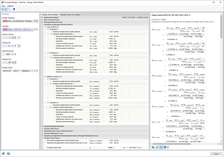
You can see detailed results in the central area, and design check formulas in the right column.
Display
In the section on the left, you can specify the parameters of the table row that is selected when opening the dialog box. Thus, you can check the design situation, governing objects, and the design criterion.
If you want to check the details of a different case configuration, you can always adjust the parameters in the selection lists – design situation, loading, object, x-location or mesh nodes, design. There are selection options for all calculated result types. For example, if you only design members, there are no options available for member sets and surfaces. Furthermore, you cannot switch to the member design checks in the Design Check Details of surfaces. In this case, select the corresponding result table in the program without closing the "Design Check Details" dialog box.
If you want to check the results of another object, you can remove the member or surface by clicking the
![]() button in the work window.
button in the work window.
For the results of a member set, only the member numbers belonging to this member set are available for selection in the list of members. When activating the
![]() button for a member set, the "Member Location x" refers to the start of the member set. If it is inactive, the x-location refers to the start of the selected member. The members designed without a member set are available in the list if you select the "--" entry for "Member Set No."
button for a member set, the "Member Location x" refers to the start of the member set. If it is inactive, the x-location refers to the start of the selected member. The members designed without a member set are available in the list if you select the "--" entry for "Member Set No."
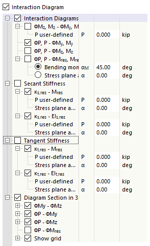
In the member design check details of the cross-section resistance, you have the option to display the relation between the design internal forces in an interaction diagram. Select the "Interaction Diagram" check box and define the parameters for this diagram.
You can evaluate the diagram in the Interaction Diagram tab.
Design Check Details
The most important input parameters, intermediate values, and design results are listed in a tree structure in the Design Check Details tab in the central area (see the image Design Check Details of Longitudinal Reinforcement). This allows you to understand the details of the design checks carried out and of the determined reinforcement area.
You can also check the intermediate values in the design formulas on the right. When clicking into a row of the "Design Values" category, the corresponding design formula is highlighted in the frame.
Design Checks in Location
In the Design Checks in Location tab, all design checks performed at the x-location or on mesh points are listed. It gives you a quick overview of the design ratios of the various design types.

If you click in a row, the corresponding design formula is displayed on the right. Double-click a row to open the "Design Check Details" tab, where you can check the intermediate values and design results.
Interaction Diagram
The Interaction Diagram tab is available in the Design Check Details of members, provided that you have activated the "Interaction Diagram" check box in the "Display" section (see the image Defining Parameters for Interaction Diagram).

The interaction diagram shows which configurations of bending moments and axial forces lead to reaching the load-bearing capacity
of the reinforced cross‑section. This information can be used as a design basis for the ultimate limit state design.
In the "Display" dialog box section, specify which interaction diagram should be displayed. In addition to the interaction diagrams related to the cross-section axes (My-N and Mz-N), you can generate an individual moment vector to create an Mres-N interaction diagram. Furthermore, you can display the "Secant Stiffness" and "Tangent Stiffness" graphically and as a table. Use the "Diagram Section in 3D" check box to control whether the section plane is also visualized in a three-dimensional interaction diagram.
To the right of the two-dimensional diagram, the value pairs of the ultimate limit state are displayed in a table. This table is dynamically linked to the diagram so that the selected limit point is also displayed in the diagram.
Design Check Formulas
The right section shows the main formulas for determining the intermediate values, as well as the final calculation of the design criterion. When you click a formula, the corresponding row is selected in the "Design Values" category in the Design Check Details. Use the
![]() button at the bottom to switch between the formula symbols and numerical values, or the
button at the bottom to switch between the formula symbols and numerical values, or the
![]() button to display a short version with the design equation.
button to display a short version with the design equation.
You can also use the design formulas in the documentation. The
![]() list button provides you with various printout options.
list button provides you with various printout options.
The
![]() button allows you to switch between the formulas and the model view. This way, you can quickly localize the design location in the model.
button allows you to switch between the formulas and the model view. This way, you can quickly localize the design location in the model.
Menu "View" and "Options"
The "Design Check Details" dialog box provides the menu functions to open further dialog boxes in order to evaluate the results or to control the view. As an alternative, you can use the corresponding buttons. The buttons have the following functions:
| Button | Function |
|---|---|
|
|
Synchronizes design check details with the selected objects in the table |
|
|
Synchronizes the result table with the selection of design check details |
|
|
Shows or hides the colored relation scale in the Design Checks in Location tab |
|
|
Opens the Result Diagrams in Section window |
|
|
Opens a window with the information about the concrete material properties |
|
|
Opens a window with the information about the cross-section properties |
|
|
Opens the Result Diagrams dialog box |