In the Surfaces tab of the "Ultimate Configurations" dialog box, you can make basic settings for the ULS design of surfaces.
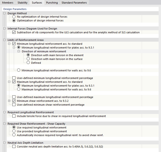
The "Design Parameters" are divided into several categories.
Design Method
When determining the required reinforcement, the principal internal forces are transformed into design forces (in the direction of the reinforcements) and into a developing concrete compression strut force. These design forces depend on the presumed angle of the concrete compression strut that braces the reinforcement mesh.
For the load situations "tension-tension" and "tension-compression" (see Image 2.18 in Online Manual of RF‑CONCRETE Surfaces), the design force may be negative in a reinforcement direction for a certain compression strut inclination; that is, there would be compressive forces for the tension reinforcement. Using "Optimization of design internal forces", the direction of the concrete compression strut is changed until reaching zero negative design force. An analysis is performed to determine which inclination angle of the concrete compression strut leads to the most favorable design result. The design moments are determined iteratively with the adjusted inclination angles in order to find the energetically smallest solution with the least required reinforcement. This optimization process is described in the Manual of RF-CONCRETE Surfaces, using an example.
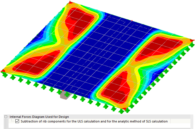
Internal Forces Diagram Used for Design
It is possible to model a T-beam by using a surface and an eccentrically connected member of the "Rib" type. The internal forces of the T-beam from the surface component and member are determined as the rib internal forces by integrating the surface internal forces. Using the "Subtraction of rib components for the ULS calculation" option, you can control whether the surface internal forces assigned to the rib are taken into account when designing the surfaces. The design without the rib component is set by default; the internal forces are included in the member design.
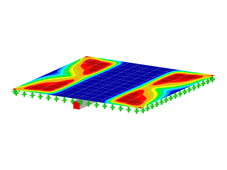
The following image shows how the subtraction affects the required surface reinforcement in the area of a rib member. The internal forces covered by the member design in the integration width are not taken into account in the surface design.
Limits of Reinforcement Areas
In this category, you can adjust the reinforcement percentage for the longitudinal and shear reinforcement and thus influence the determination of the required reinforcement.
Specify whether the configuration should control the "minimum longitudinal reinforcement for plates acc. to 9.3.1" or the "minimum longitudinal reinforcement for walls acc. to 9.6". The specific subitems are only displayed for the activated option – plates or walls.
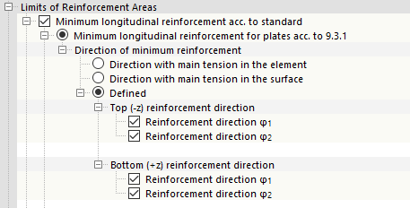
Minimum Longitudinal Reinforcement for Plates
Three options are available for the minimum reinforcement of plates.
- "Direction with main tension in the element": The main tension force is determined element by element in each direction and for each side. The minimum longitudinal reinforcement is taken into account for this direction and side with the main tension force per element.
- "Direction with main tension in the surface": The main tension force is determined for the entire surface and taken into account for the minimum reinforcement.
- "Defined": You can directly specify for which direction and side of the surface the minimum longitudinal reinforcement is to be applied.
Minimum Longitudinal Reinforcement for Walls
In the case of the minimum reinforcement for walls, you can select whether the minimum longitudinal reinforcement according to 9.6 should be entered either in the "reinforcement direction with the main compression force" or "defined in reinforcement direction".
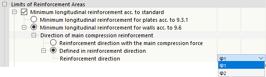
In contrast to the reinforcement for plates, you only need to specify the direction. It is not necessary to select the sides, because the same reinforcement is available on both sides of the surface.
User-Defined Minimum Longitudinal Reinforcement Percentage
In addition to the standard specifications, you can also manually specify the minimum longitudinal reinforcement percentage. If you select the check box, additional lines appear where you can define the minimum longitudinal reinforcement content in percentage.
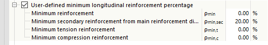
The "minimum secondary reinforcement from the main reinforcement direction" ρmin,sec is coupled to the calculated longitudinal reinforcement in Direction 1. For the reinforcement in Direction 2, the reinforcement percentage of 20% is set by default.
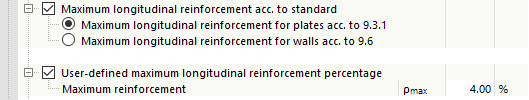
Maximum Longitudinal Reinforcement acc. to Standard / User-Defined Maximum Longitudinal Reinforcement Percentage
In these categories, you can specify the maximum longitudinal reinforcement according to the standard for plates or walls or define it manually in the same way as the minimum longitudinal reinforcement.
Minimum Shear Reinforcement
The check box controls whether to arrange a minimum shear reinforcement according to 9.3.2. For DIN EN 1992‑1‑1, you can specify the "Ratio b/h", as of which this minimum reinforcement is relevant.
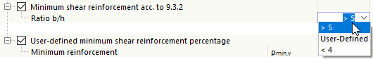
This distinction is based on the following consideration: First, it is not known whether the surface is a surface or a member-shaped component (in RFEM, a beam can also be modeled as a surface component). The utilization of the shear reinforcement of a plate or the shear reinforcement of a beam for the structural component depends on the ratio of width to height of the component: It determines whether there is a surface (b/h > 5) or a beam (b/h < 4). If the ratio is less than 4, the program automatically switches to the minimum shear reinforcement for beams. Since the National Annex allows you to interpolate the values for the range 5 ≥ b/h ≥ 4, you can also specify a "User-Defined" value. The program then interpolates between the values to reduce ρw,min between 1.0 for beams and 0.60 for plates.
User-Defined Minimum Shear Reinforcement Percentage
You can also define a user-defined value for the minimum shear reinforcement, which may override the minimum shear reinforcement according to the standard.
Required Longitudinal Reinforcement
The truss analogy in shear design results in an additional longitudinal force in the tension reinforcement – as in the case of the tension covering line or the shift rule in a frame & truss analysis. If you want to take this additional tensile force into account when determining the required reinforcement, select the "Include tensile force due to shear in required longitudinal reinforcement" check box.
Required Shear Reinforcement - Shear Capacity
The longitudinal reinforcement percentage ρl of a surface is included in the determination of the shear capacity νRd,c. You can use the selection boxes in this category to control which longitudinal reinforcement percentage should be considered at each FE mesh node or grid point when determining the shear capacity νRd,c.
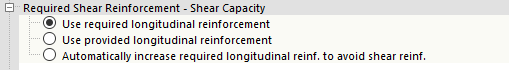
- "Use required longitudinal reinforcement": To determine the shear capacity νRd,c, the statically required longitudinal reinforcement from the bending design is applied. This means that the longitudinal reinforcement percentage ρl can differ from an FE mesh point to an FE mesh point or from a grid point to a grid point.
- "Use provided longitudinal reinforcement": The program applies the sum of the provided surface reinforcements for each FE mesh point or grid point. The upper limit of the longitudinal reinforcement is ρmax.
- "Automatically increase required longitudinal reinforcement to avoid shear reinforcement": The program increases the required reinforcement from the bending design at the FE network points or grid points until no more shear reinforcement is required at this point. If, despite this increase, the shear reinforcement cannot be avoided at the respective node, the longitudinal reinforcement would not be increased. In the required reinforcement diagram, you can see whether the shear reinforcement has been avoided using this function: In that case, the required reinforcement is not based on the bending design, but on the shear design.
Neutral Axis Depth Limitation
The check box in this category controls whether the design of the neutral axis depth limitation should be performed.
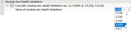
When activating this check box, you can specify the ratio xd/d for the neutral axis depth limitation. A ratio of xd/d = 0.45 is set by default. There is no automatic adjustment for higher-quality concrete grades. For the concrete compressive strength classes as of C55/67, you should thus set the limit value manually, taking into account the National Annex, or select the appropriate entry from the list.