


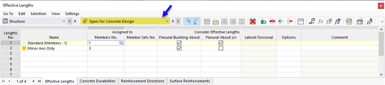
The essential boundary conditions for the design are defined by assigning "Types for Concrete Design" to the object to be designed (a member, a surface, a node). You can use various options to do this:
- Enter numbers of the relevant members, member sets, surfaces, or nodes in the dialog boxes of the individual types (see the image Effective Lengths ).
- Enter the object numbers in the "Types for Concrete Design" input tables (available in the main category Structure).
- Assign the type in the tabs of the design properties in the object dialog boxes.

By activating Concrete Design, the design properties are activated for all members and surfaces that use the material of the Concrete type. The available "Types for Concrete Design" depend on the standard . They are described in the following chapters.
Select an existing Type for Concrete Design from the list (see the image Assigning Concrete Durability Type). The
![]() button allows you to create a new type. Click the
button allows you to create a new type. Click the
![]() button to graphically select another object in order to use its properties for the concrete design. To edit the selected type, use the
button to graphically select another object in order to use its properties for the concrete design. To edit the selected type, use the
![]() button.
button.
You can also display the Types for Concrete Design graphically in the model. The corresponding display options can be found in the "Types for Concrete Design" category in the Navigator – Display. This allows you to easily check whether the types are assigned correctly.
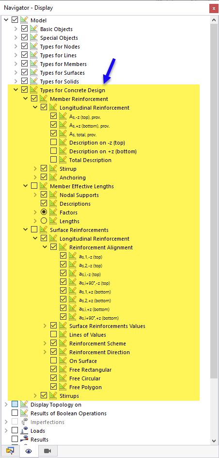
The options in the Navigator also provide the opportunity to prepare the graphic for documentation in the graphic printout.