The Stability tab of the "Ultimate Configurations" dialog box controls the configuration for the stability analysis of columns. This design is based on the nominal curvature method. It is automatically performed in the form of section design, provided that the effective lengths are assigned to the relevant members.
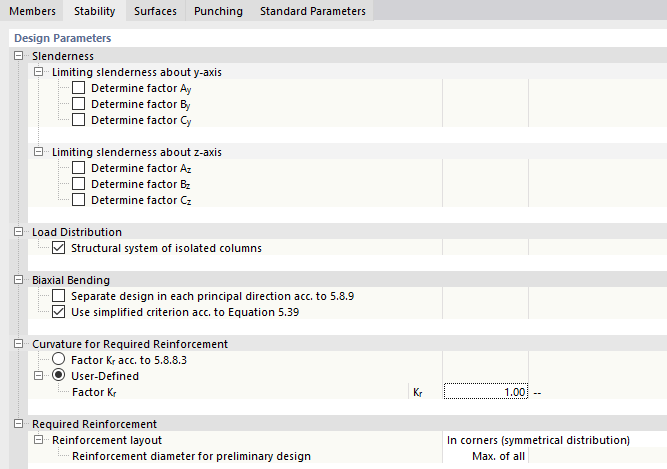
Slenderness
This category is displayed for National Annexes which require the definition of a slenderness limit for the individual compression elements. The factors A, B, and C are included in the determination of the slenderness limit λlim according to Equation (5.13N). They can either be determined by the program or user-defined. The recommended values are set by default.
Load Distribution
In this category, you can define whether the structural system consists of "isolated columns" or several effective columns.
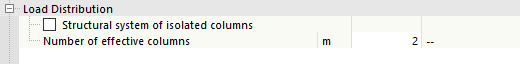
If you have a combined structure consisting of isolated columns and connected column structures, create different configurations and assign them to the corresponding columns.
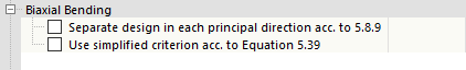
Biaxial Bending
The design of a model column is generally carried out while taking into account biaxial bending. If you want to carry out a "separate design in each principal directions acc. to 5.8.9" or "use simplified criterion acc. to Equation 5.39", select the corresponding check box.
Also in this case, it is necessary to create different configurations and assign them to different specifications for members of the model.
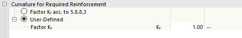
Curvature for Required Reinforcement
In order to determine the eccentricities according to the second-order analysis for the nominal curvature method, the curvature is taken into account in the program using the factor Kr. This can either be determined automatically according to 5.8.8.3, or user-defined.
Required Reinforcement
In the stability analysis based on the nominal curvature method, the internal forces are determined with the specified effective length, taking into account the eccentricities according to the second-order analysis. These internal forces are used to design the cross-section with the provided reinforcement. Regardless of this, the program can also determine the required reinforcement value if the defined provided reinforcement is too small. To do this, you need to specify the sides of the cross-section on which the required reinforcement is to be applied or determined. You can select the relevant position from the list.
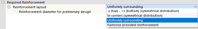
Note that this setting has an impact on the determined value of the required reinforcement. This applies especially to a structural component that is primarily loaded by the moment My or Mz. In this case, it is reasonable to distribute the reinforcement symmetrically above and below (for My) or to factorize the provided reinforcement in order to take into account the relatively large moment Mz.
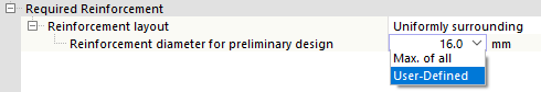
For columns, however, which are subjected to approximately equal loads in both main axis directions and where My and Mz are of a similar magnitude, the option "Uniformly surrounding" or "In corners (symmetrical distribution)" is recommended.
The "Reinforcement diameter for preliminary design" option controls which diameter is used when determining the required reinforcement described above. The largest cross-section of the provided reinforcement is used ("Max. of all") by default. You can also define a different value by selecting the "User-Defined" option and specifying the reinforcement diameter.