In the Shear Reinforcement tab, you can define the stirrup reinforcement to be used for the shear design of the member.

Fields
This section provides the option to define ranges for the stirrup reinforcement. Only one entry is preset here, representing a kind of "basic reinforcement". You can adjust this default and divide the one large 'field' into segments (see image Define shear reinforcement). Use the
![]() button at the end of the list to create new fields.
button at the end of the list to create new fields.
For the graphical representation of the stirrup reinforcement, it may be necessary to specify an 'offset' for the edge distances of stirrups.
Parameters
In this section, you can specify the properties of the shear reinforcement. The parameters always refer to the field selected in the 'Fields' list on the left.
Basic Data
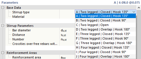
Select the 'Stirrup type' from the list. Various stirrup shapes are available.
Assign a Material to the stirrup reinforcement. If you have already defined the suitable reinforcing steel in the model, it is available for selection in the list. Otherwise, you can create a new material via the
![]() button in the input field by accessing the material library in the
New Material
dialog.
button in the input field by accessing the material library in the
New Material
dialog.
Stirrup Parameters
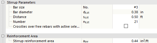
Define the 'Rebar diameter' ds,st of the stirrups, the 'Distance' ss,st between the stirrups, or the 'Number' ns,st of stirrups in the field. Usually, you specify the diameter of the stirrups ds,st and the distance ss,st. The stirrup number is determined automatically from this. However, you can also specify the number of stirrups ns,st. The program then determines the appropriate distance for the field. You can read the reinforcement area of the existing stirrup reinforcement in the category below.
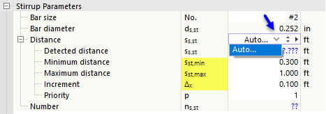
If the program is to design the diameter or the number during the design, select the Auto option.

If the Rebar diameter has to be determined, you can specify the smallest and largest possible diameter for the design. A user-defined list of possible diameters allows you to restrict the stirrup reinforcement to specific bar diameters.
If the program has to determine the Distance, define the minimum and maximum permissible stirrup spacing as well as the increment Δx for the design process.
Reinforcement Areas
The reinforcement cross-section resulting from the parameters of the 'Stirrup Reinforcement' section is displayed here. Alternatively, you can specify the reinforcement area asw directly in [cm2/m] or [in2/ft]. From this, the program determines the required distance ss,st and the resulting number ns,st of stirrups. The diameter ds,st remains unchanged.
Position of Field
In this category, you specify where the 'Field' with the stirrup reinforcement is arranged in the member. You can define this position with a 'Reference' to the start, the end, or an x-location. Select the appropriate option in the list to define the reference point for the position of the field.

Furthermore, you can control with the 'Definition format' whether the distances are to be defined absolutely in length units or relatively in percentages.
Enter the 'Start' x1 and the 'End' x2 of the field. The 'Span' ls of the field thus represents the length of the stirrup segment in the member.
Edge Distances of Stirrups
The 'Arrangement rule' controls how the stirrups are positioned at the edges of the field. Several variants are available for selection.
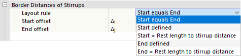
With the default 'Start equals End', the program determines a residual length from the number ns,st and the distance ss,st of the stirrups, which is applied in equal parts at the start and at the end of the field. The input fields for Δi and Δj are locked.
With the other options, you can define the edge distances of the stirrups manually:
- 'Start defined': Enter the start offset Δi, which defines the position of the first stirrup in the field. The distance Δj at the end of the field is determined automatically; this value is not editable.
- 'Start = Residual length to stirrup spacing': This option is not possible for the first field, but only for following fields. With this rule, the distances Δi and Δj are determined automatically; the values are not editable. If you delete the previous field, the option is automatically changed to 'Start defined' and the previously determined value is entered as the start offset Δi.
- 'End defined': Enter the end offset Δj, which defines the position of the last stirrup in the field. The distance Δi at the start of the field is determined automatically; this value is not editable.
- 'End = Residual length to stirrup spacing': The program does not apply a start offset. From the distance ss,st of the stirrups, the possible number of stirrups ns,st is determined and the residual length at the end of the field is defined.
Information
Finally, you can find the following information about the stirrup reinforcement of the current field:
- Length of one stirrup Lst,1
- Length of all stirrups Lst as sum
- Weight of one stirrup Wst,1
- Weight of all stirrups Wst as sum
Graphic
In the two graphic areas of the tab, the reinforcement is displayed graphically: On the right, you see the cross-section of the member, at the bottom the longitudinal section. Your entries are implemented dynamically there, offering a good control option.

Cross-section
The graphic on the right shows the cross-section of the member with the defined stirrup and longitudinal reinforcement. The concrete cover is considered for the reinforcement arrangement. The local axes z and y of the member are also displayed in the cross-section graphic.
The cross-section graphic refers to the reinforcement at the 'Location x' along the member, which is specified in the field below the graphic. With the default setting x = 0.000 m, the reinforcement at the member start is displayed. To display the reinforcement at another member location, enter the corresponding distance. The location x is then marked with an arrow in the longitudinal section.
The buttons below the graphic have the following functions:
|
|
Switches between cross-section graphic and model view |
|
|
Displays only the longitudinal reinforcement selected in the Positions list |
|
|
Shows or hides the member axes |
|
|
Shows or hides the dimensioning of the cross-section |
|
|
Allows printing the graphic in various variants |
Longitudinal Section
The graphic in the lower area of the dialog shows the longitudinal section of the member with the defined stirrup and longitudinal reinforcement, as well as the support symbols from the defined effective lengths and design supports.
For working in this graphic area, you can use all mouse functions described in the chapter Graphic Control of the RFEM manual. This allows the reinforcement of the member to be displayed zoomed or spatially.

The buttons next to the graphic have the following functions:
|
|
Allows setting the view in various variants |
|
|
Allows the display in different member axis directions |
|
|
Allows representation as wireframe, solid, or transparent model |
|
|
Allows showing and hiding various auxiliary and model objects |
|
|
Displays the member symbolically horizontally or in real position |
|
|
Allows printing the graphic in various variants |
|
|
Opens the Reinforcement Arrangement window |
|
|
Displays the overall view of the member |