


The standard-specific parameters are organized in the "Edit Serviceability Configuration" dialog box. There, you can manage the settings for members and surfaces together.
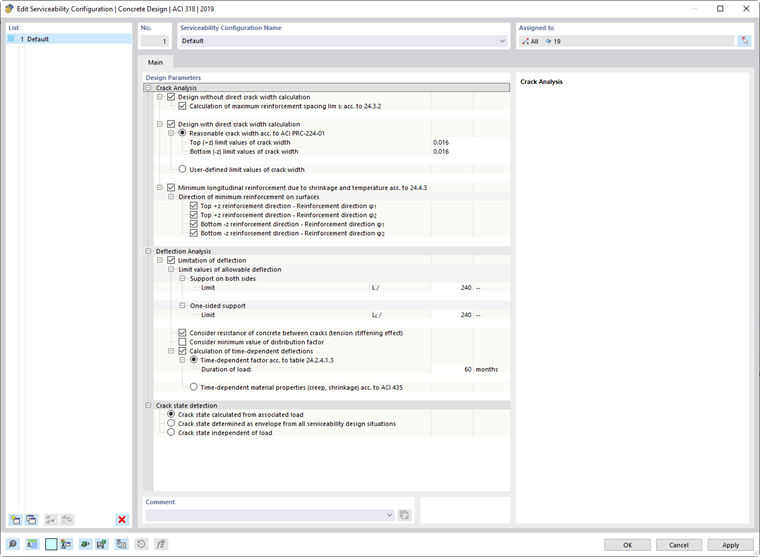
The "Design Parameters" are divided into several categories where you can make your adjustments.
Deflection Analysis
If the “Limitation of deflection” check box is selected, the program checks the structural components with regard to allowable limit values and issues a corresponding design criterion. The support conditions of the structural components play a decisive role here.
In the “Limit values of allowable deflection” category, the limit value for the design is preset to L/240 for a “Support on both sides” and to Lc/240 for a “One-sided support”.
If you select the “Consider resistence of concrete between cracks (tension stiffening)” check box, the stiffening effect of the concrete in tension between cracks is taken into account in the deflection analysis. This effect is also referred to as “tension stiffening”: In cracked reinforced concrete components, the tensile forces in the crack are absorbed by the reinforcement alone, but tensile stresses are introduced into the concrete between two cracks via the (displaceable) coupling. The concrete thus participates in the absorption of internal tensile forces, which leads to an increase in the stiffness of the structural component.
In the analytical deformation analysis, the damage to the concrete cross-section in the cracked state is taken into account via the distribution coefficient ζ. This coefficient is determined automatically from the load situation element by element or x-location by x-location. If you select the “Consider minimum value of distribution factor” check box, you can specify a minimum value for ζ, for example, to apply a “minimum damage” at locations with zero moment crossings that would not result from the defined load.
By activating the “Calculation of time-dependent deflections” check box, the time-dependent concrete effects (creep and shrinkage) are included in the deformation analysis. The time-dependent concrete effects can be taken into account either by using a time-dependent factor according to Table 24.2.4.1.3 (ACI 318-19) or by using time-dependent material properties (creep and shrinkage) according to ACI 435.
Time-Dependent Factor According to Table 24.2.4.1.3
The time-dependent factor ξ is determined as a function of the load duration t. According to ACI 318-19, Table 24.2.4.1.3, a linear interpolation is used for load durations between 12 and 60 months:
- ξ = 1.4 for t = 12
- 𝜉 = 2.0 for t = 60 months
It is necessary to enter the load duration in the serviceability configuration.

The long-term factor λΔ for considering creep and shrinkage is determined according to ACI 318-19 as:
\( \lambda_\Delta = 1 + \dfrac{\xi}{1 + 50 \cdot \rho'} \)
The final deflection at the considered location results from multiplying the immediate deflection by the long-term factor:
\( u_z = u_{z,\mathrm{total}} \cdot \lambda_\Delta \)