The result tables of the Reinforcement on Members category list the required reinforcement cross-sections, which result from the internal forces of the ultimate limit state design situation. If the longitudinal reinforcement has been increased automatically to fulfill the serviceability limit state design (see Chapter Basic Settings ), these reinforcement cross-sections are also taken into account. In the same way, the reinforcement to fulfill the construction rules is covered if the minimum longitudinal reinforcement according to the standard has been activated (see Chapter Members ). The extreme values of each reinforcement type are marked with colored dots in the rows.

The available reinforcement cross-sections as well as the uncovered reinforcement are specified in further tables.

The member results are sorted in the tabs according to the following criteria:
- Objects (member locations x, members, member sets)
- Member properties (cross-sections, materials)
Member No. / Member Set No.
For each extreme value of the reinforcement, the number of the governing member or member set (if designed) is shown.
Node No.
The results are displayed for each start and end node of the designed members.
Location x
The x-location in the member for which the maximum reinforcement was determined is specified in each case. The following locations x are relevant to the tabular output:
- Start and end nodes
- Member result intermediate points (if defined)
- Member division according to the mesh settings for members
- Extreme values of internal forces
Design Situation
This column shows the numbers of the design situations with the individual reinforcement available.
Loading
This column shows the numbers of the load or result combinations that are governing for the respective reinforcements.
Longitudinal Reinforcement
The following results are displayed for the longitudinal reinforcement:
| Reinforcement | Description |
|---|---|
| As,-z (top) | Cross-section of the top longitudinal reinforcement due to axial force, or bending with or without axial force |
| As,+z (bottom) | Cross-section of the bottom longitudinal reinforcement due to axial force, or bending with or without axial force |
| As | As,-z (top) + As,+z (bottom) |
| As,T | Cross-section of the torsional longitudinal reinforcement |
| As,tot,-z (top) | As,-z (top) + As,T/2 |
| As,tot,+z (bottom) | As,+z (bottom) + As,T/2 |
| As,tot | As + As,T |
Stirrup Reinforcement
The following results are displayed for the stirrup reinforcement:
| Reinforcement | Description |
|---|---|
| asw,V | Cross-section of the shear reinforcement for the shear force, in relation to the unit length of 1 m |
| asw,T | Cross-section of the shear reinforcement for the torsional moment, in relation to the unit length of 1 m |
| asw,tot | asw,V + asw,T |
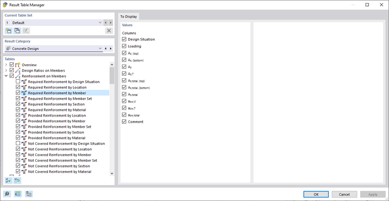
You can use the Result Table Manager to specify which columns should be displayed in each table.