


The stability analysis of members according to the model column method or the nominal curvature method requires the definition of effective lengths. If you assign an effective length to a member, the corresponding boundary conditions and effective lengths are taken into account for the stability analysis of the member. The cross-section design is then carried out with the internal forces of this stability analysis.

Main
In the "Main" tab, you can make basic specifications. The effective length factors and the support conditions are entered in the Nodal Supports & Effective Lengths tab.
Determination Type
Use the check boxes to specify which forms of stability failure are to be checked for the member (or the member set). Under compression, flexural buckling about the major or minor axis can become governing.
If you deactivate a failure mode, the corresponding option is deactivated in the "Structure Type" tab and in the "Nodal Supports & Effective Lengths" tab. This failure type is then not analyzed in the design.
Structure Type
In this section, select the relevant option to determine whether the structural system of the member is "Unbraced" or "Braced". You can specify this separately for both buckling directions. The Structure Type affects the determination of the equivalent moment M0e according to EN 1992‑1‑1, 5.8.8.2(2), Eq. (5.32).
Options
The "Import from Stability Analysis" check box allows you to apply the effective length factors based on buckling modes. You can make the corresponding entries in an additional tab Import from Stability Analysis.
Nodal Supports & Effective Lengths
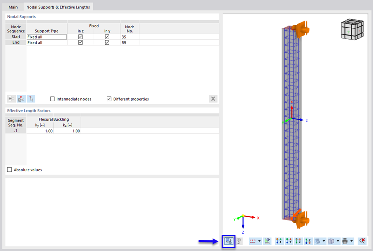
In the Nodal Supports & Effective Lengths tab, you can define boundary conditions for the stability analysis and define the effective length factors.
Nodal Supports
The member (or member set) support defines the boundary conditions for the stability analysis. Furthermore, the nodal supports are used to subdivide the member into segments.
To define the supports, you can select typical variants from a list in the "Support Type" column. As an alternative, you can individually check (a fixed support) or uncheck (no support) the boxes in the "Fixed" column.
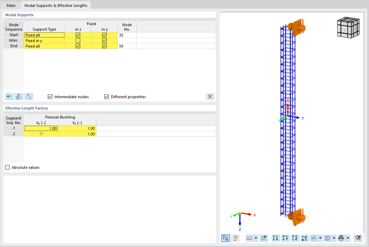
You can define the nodal supports for the start and end of the member. If the member is supported by a node on the member itself, select the "Intermediate nodes" check box (see the image Defining Effective Length Factors by Segment). Standard nodes between members of member sets and nodes of the "On Member" type are considered as intermediate nodes (see Chapter Nodes of the RFEM manual).
The definition of intermediate nodes is not based on node numbers, but on the order on the member: .1 designates the first intermediate node from the member start, .2 the second intermediate node, and so on. If a member to which this effective length is assigned has more or fewer intermediate nodes, they are taken into account from the member start; excess entries or nodes are ignored.
Using the
![]() button, you can insert a new intermediate node above the selected line. To delete an intermediate node, select the line and click the
button, you can insert a new intermediate node above the selected line. To delete an intermediate node, select the line and click the
![]() button. The table shortcut menu also provides the options for editing rows.
button. The table shortcut menu also provides the options for editing rows.
Use the
![]() button to select a member or a member set in the model in order to transfer its number of intermediate nodes to the table. If the effective length is already assigned to a member, you can select a node by clicking the
button to select a member or a member set in the model in order to transfer its number of intermediate nodes to the table. If the effective length is already assigned to a member, you can select a node by clicking the
![]() button. In the table, the row of the associated intermediate support is selected (if available).
button. In the table, the row of the associated intermediate support is selected (if available).
Once the effective length has been assigned to a member, you can check the supports and axes using the
![]() button in the dialog box graphic (see the image Defining Nodal Supports and Effective Lengths).
button in the dialog box graphic (see the image Defining Nodal Supports and Effective Lengths).
Effective Length Factors
The "Effective Length Factors" table is adjusted to the number of the nodal supports. If no intermediate nodes are defined, there is only one "segment." You can adjust the effective length factors of this segment to fit the boundary conditions by extending or shortening the effective length for the various failure modes using coefficients.
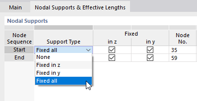
Supports at the intermediate nodes (see the image Selecting Support Type) subdivide the member or member set into several segments for various failure cases:
- None: The effective length factor from Segment No. 1 applies to all following segments.
- Fixed in z: Individual effective length factors ky for buckling around the y-axis
- Fixed in y: Individual effective length factors kz for buckling around the z-axis
- Fixed all: Individual effective length factors for both buckling directions and all segments
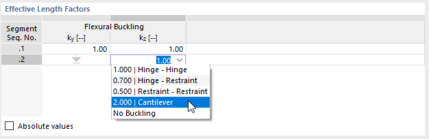
An arrow symbolizes an effective length factor across segments if there is no corresponding intermediate support in the "Nodal Supports" table. You can define the effective length factors of the individual segments in the table rows, and thus adapt the effective lengths of the sections.
The effective length used for the design of a failure mode at a location in this segment results from the multiplication of the segment length by the corresponding effective length factor.
|
Lcr |
Effective length |
|
k |
Effective length factor |
|
L |
Member or segment length |
For each segment, enter the effective length factors that are governing for the buckling around the y or z axis. Typical effective length factors can also be selected from the list.
You can also specify "absolute values" for the effective lengths. Please note that these values are used for all assigned objects. Unlike with effective length factors, there is no relative adjustment to the actual segment length! Therefore, it is preferred to use the definition via effective length factors instead of absolute values.
The automated determination of the effective lengths for concrete structures using the kA-kB method is not yet available at the current stage of development.
Import from Stability Analysis
The Import from Stability Analysis tab is available once you have activated the corresponding check box in the Main tab. Here, you can select the buckling modes and members whose effective length factors ky or kz should be applied.

About Axis
The mode shapes are properties of a load case or a load combination. First, select in the "Load Case / Load Combination" list, which load situation is governing for the buckling mode. The list only contains those load cases and load combinations with a specified stability analysis. You can define a mode shape of a specific load case for each principal axis.
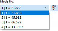
In the next step, define the governing "Mode No." The list of mode shapes is available for all calculated load cases and load combinations.
Click the
![]() button to display the mode shapes in the work window.
button to display the mode shapes in the work window.
Finally, select the "Member No." in the list. You can also use the
![]() button to define the member graphically in the work window.
button to define the member graphically in the work window.
Effective Length Factors
The table shows the effective length factors that were imported from the stability analysis for both principal axes. If you want to adjust the value, select the "User-Defined" check box in the "About Axis" section. Thus, the text box becomes accessible.
The effective length factors displayed here are transferred to the Nodal Supports & Effective Lengths tab and can no longer be edited there. The "Absolute Values" option allows you to transfer the effective lengths Lcr,y and Lcr,z of the members from the stability analysis results. You can use this option, for example, if you want to apply the effective length to a member set from a member included therein.