


In this dialog box, the seismic configurations are managed; that is, the detailed settings for the seismic design of structural components.
For the design of structures for earthquake resistance according to the Eurocode, the rules of EN 1998‑1 [1] apply. For the design of concrete structures, the rules of EC 8 are applied in addition to the rules of EN 1992‑1‑1:2004.
The following image shows the dialog box for editing the seismic configurations for EN 1998‑1 [1]. The reduced view of the settings clearly shows the outline of the seismic configurations.

The following text shows and describes the individual sections of the configurations.
Ductility Class
In this section of the dialog box, you can specify the ductility classification for the assigned objects.
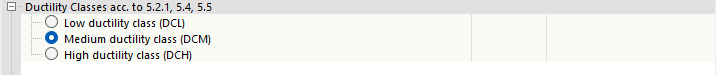
The higher the ductility class, the smaller the equivalent seismic loading. However, the higher the ductility class, the higher the demands on the structural design to ensure the ductility. In the following text, the configurations for the "high" ductility class are shown, as they have the greatest scope. For the "medium" and "low" ductility classes, on the other hand, some of the check boxes are omitted.
Type of Structural System
This section allows you to assign a type of the structural system to the assigned structure, depending on its structural behavior under horizontal seismic action.
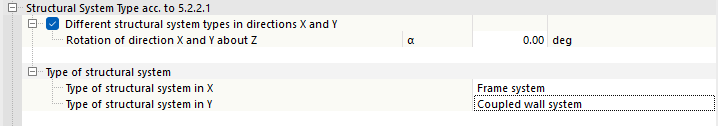
Different structural system types in directions X and Y
Use this option to define whether to assign different structural types to the structure for the X- and Y-directions. When activating this option, you can also specify a rotation angle α. You can use it, if necessary, to adjust the angle between the horizontal main support directions of the structure and the horizontal axes of the global coordinate system.
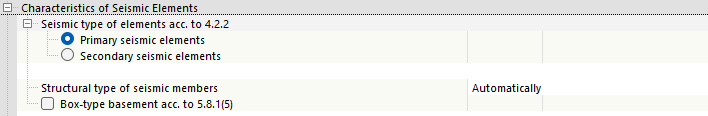
Properties of Seismic Elements
In this section, you specify whether the structural elements are to be classified as primary or secondary, with regard to their participation in the transfer of seismic loads. Furthermore, it is possible to assign the seismic component type for members.
Partial Safety Factors for Materials
Regarding the partial safety factors, you can select the design situation of the ultimate limit state according to which the partial factors should be applied. You can select between the permanent and temporary design situations, as well as the accidental design situation.

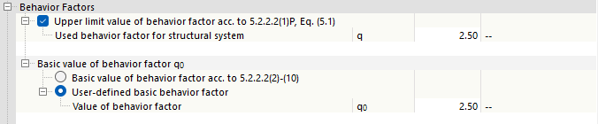
Behavior Factors
In this area, you can activate the design of the limit value for the behavior factor. When activating the design, you can import the used existing behavior factor from the defined response spectrum on which the dynamic loads are based. As an alternative, you can define the existing behavior factor manually.

You can also decide whether the basic value of the behavior factor according to the standard should be determined in the program, or defined manually.
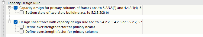
Capacity Design Rule
These settings allow you to activate or deactivate the capacity design checks. Furthermore, you can manually define post-limit stress factors, if necessary.
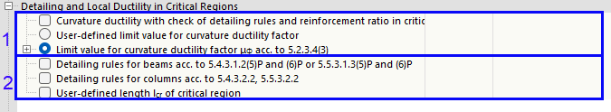
Detailing and Local Ductility in Critical Regions
In this part of the configuration, you can control all design checks of the construction rules. Here, it is possible to activate the design checks of sufficient curvature ductility factor – see (1) in the following image – as well as of detailed design – see (2).
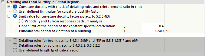
Curvature Ductility Factor
For the design of sufficient curvature ductility factor, there is the option to perform an indirect analysis using the detailing rules. Furthermore, you can select whether the limit value of the curvature ductility factor should be user-defined or defined according to the standard.
In order to determine the limit value of the curvature ductility factor according to the standard, you have the option to import the periods Tc and T1 from the defined response spectrum on which the dynamic loads are based. As an alternative, you can define the values of the periods manually.
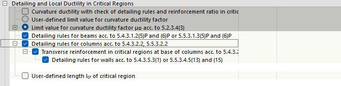
Structural Detailing
These options allow you to activate detailed structural design checks to ensure local ductility.
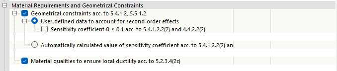
Material Requirements and Geometrical Constraints
In this section, you can control the design of the material requirements and geometric conditions. Geometrical conditions are required according to EN 1998‑1 for the ductility classes "medium" and "high". Requirements for material properties are to be checked for all ductility classes.
Required Reinforcement
You can use this check box to control whether the performed design checks of the seismic design situation should be taken into account for the reinforcement design.
Currently, the capacity design checks are not considered in the determination of the required reinforcement.
