


In the Members tab of the "Ultimate Configurations" dialog box, you can make basic settings for the ULS design of members and member sets.

The "Design Parameters" are divided into several categories.
Consider Internal Forces for Concrete Design
In this category, you can control the member internal forces N, My, Mz, Vy, Vz and MT for the design, and define which internal forces are taken into account in the design. By default, all forces and moments are taken into account once they exceed a certain "tolerance". You can define this value individually for each internal force type.
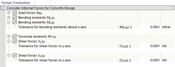
This allows you, for example, to neglect the torsional moment in the design of a rib. To do this, define a new ultimate configuration, deactivate the torsional moments MT,Ed, and use this configuration for the rib.
Reductions of Internal Forces in z-Direction
In this category, you can make the settings for the "moment redistribution", "moment reduction", or "moments at the face of a monolithic support", and the "reduction of shear forces".
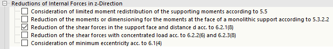
The relevant sections of the standard are indicated for the individual options. The check boxes control whether to modify the design moment My or reduce the shear force Vz in the design.
The Design Supports and Deflection chapter describes how to define supports for the concrete design and how to define the settings of a monolithic support or the ratio δ for the moment redistribution for an inner support.
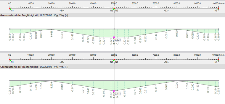
The following image shows the design ratios for the shear force design UL0200.02 with a reduction of the shear force Vz (upper diagram) and without a reduction of the shear force Vz (lower diagram).
Further information about the shear force reduction in member design can be found in the following articles in our Knowledge Base:
- Shear Force Reduction Vz (for RFEM 5; the concept also applies to RFEM 6)
- Defining Design Supports
Required Longitudinal Reinforcement
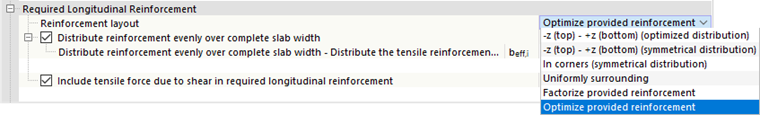
Reinforcement Layout
You can use the reinforcement layout to influence the determination of the required longitudinal reinforcement. Various options are available in the list (see the Reinforcement Layout) image.
The "Reinforcement Layout"' affects the distribution of the required longitudinal reinforcement, which is always output after the design – regardless of whether the individual design checks are fulfilled or not. If a member with the defined longitudinal reinforcement is not sufficiently dimensioned after the design, you can compare this distribution of the required reinforcement to the distribution of the provided reinforcement and use it to determine the "not covered reinforcement". It is then available as a result.
Distribute Reinforcement Evenly over Complete Slab Width
This option allows you to specify whether to use the entire slab width of the rib member (the entire chord width), or just the width of the rectangular cross-section when determining the required longitudinal reinforcement.
Include Tensile Force Due to Shear in Required Longitudinal Reinforcement
This check box controls whether to include the tensile force component due to the shear force (the tensile force cover) when determining the required longitudinal reinforcement.
Detailing and Particular Rules
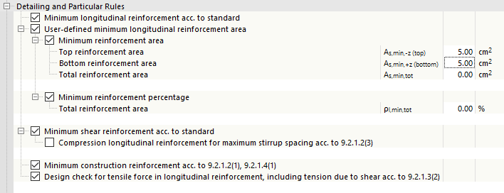
When designing members, you can optionally check the design specifications regarding the "minimum longitudinal reinforcement", the "minimum reinforcement ratio", or the "minimum shear reinforcement". If one of these design checks is not fulfilled with the given reinforcement, you can either exclude the design here or adjust the reinforcement.
Required Shear Reinforcement – Shear Capacity
There are three options to select from in order to determine the required shear reinforcement.
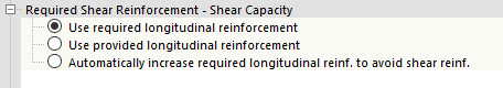
In the default setting, the statically required longitudinal reinforcement is used to determine the shear force resistance VRd,c. Since this option causes the longitudinal reinforcement ratio ρl to differ from x-location to x-location of the member, the shear force resistance along the member is not constant, but depends on the required longitudinal reinforcement.
As an alternative, you can apply the provided longitudinal reinforcement to determine the shear force resistance VRd,c. If a constant longitudinal reinforcement has been defined along the member, the applied longitudinal reinforcement ratio ρl is constant as well.
The third option allows you to increase the required longitudinal reinforcement to avoid shear reinforcement. This means that the required longitudinal reinforcement is not only influenced by the bending design, but also by the shear force design: The program increases the required longitudinal reinforcement until VEd = VRd,c.
Shear Joint
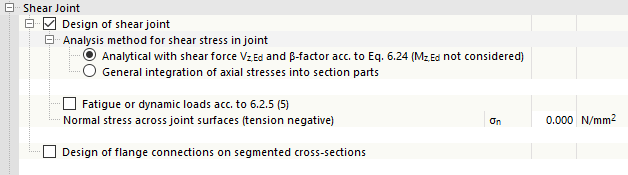
Shear Force Transfer in joints
By selecting the Design of shear joint check box, the design of joints is activated, which are present, for example, in concrete additions for precast elements. This also makes the remaining text boxes accessible for entering the parameters for the design according to EN 1992-1-1, 6.2.5.
This design is currently only available for the “rib” member type. The required input parameters for classifying the surface roughness and joint width can be entered in the member dialog box in the “Rib” section.
The chapter Shear Transfer in Joints provides further information.

Shear Force Transfer Between Beam Web and Flange
By selecting the Design of flange connections ... check box, the design for shear force transfer between the beam web and flange according to EN 1992-1-1, 6.2.4 becomes available.
The basis for this design can be found in the chapter Shear Force Transfer Between Beam Web and Flange.
Neutral Axis Depth Limitation
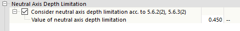
According to EN 1992‑1‑1, it is necessary to perform the neutral axis depth limitation design, depending on the analysis method (elasticity or plasticity analysis). Whether this design is carried out by default depends on the National Annex. For example, this option is activated for the design according to DIN EN 1992‑1‑1.
Calculation Setting
A gross concrete section is generally used for the section design checks. However, if you want to take into account a net section (gross section minus reinforcement section) in the section design due to a higher reinforcement ratio, for example, select the "Net concrete area" check box.