


The standards describe how actions are to be combined. EN 1990, for example, requires the verification of the ultimate and serviceability limit states, each of which is subject to specific combination rules. ASCE 7 specifies guidelines for combining load cases for strength design and allowable stress design. These regulations for limit states or design strengths can be examined in design situations (DS).

For EN 1990, one ultimate and three serviceability design situations are preset; for ASCE 7, the two design situations for "strength design" and "allowable stress design" are preset.
The Active check box controls whether the design situation selected in the list is analyzed in the calculation. This allows you to exclude design situations that are not relevant to the model from the calculation.
Use the
![]() button at the end of the 'List' to add a new design situation.
button at the end of the 'List' to add a new design situation.
Basis
The Basis tab manages the general information of the design situation selected in the 'List' on the left.
Settings
The 'Design situation type' determines the standard according to which the load cases are combined in the superposition. The selection options are adapted to the standard (see image above).
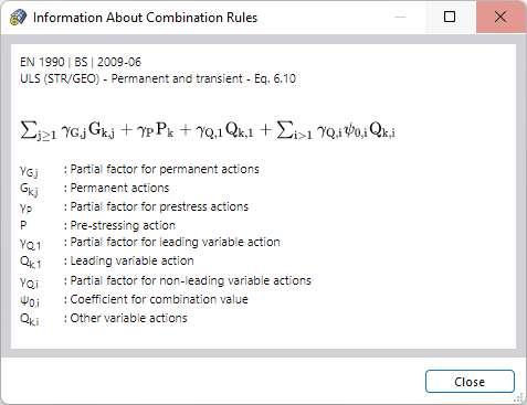
You can check the combination rule of the design situation using the
![]() button.
button.
Options
Specify which Combination Wizard is to be used for the superposition of load cases. By default, RFEM generates load combinations that are analyzed according to the second-order analysis. The Combination Wizards are described in the chapter Combination Wizards.
The Consider inclusive/exclusive load cases check box offers the option of setting up reciprocal dependencies between load cases. You can define the criteria in a separate dialog box (see chapter Load Case Relationships).
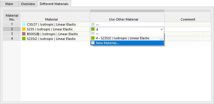
When you activate the Different Materials check box, a new tab is added. There, you can replace a material with an alternative material for the selected design situation. This is useful if, for example, you use different stress-strain diagrams for the ultimate and serviceability limit states.
Overview
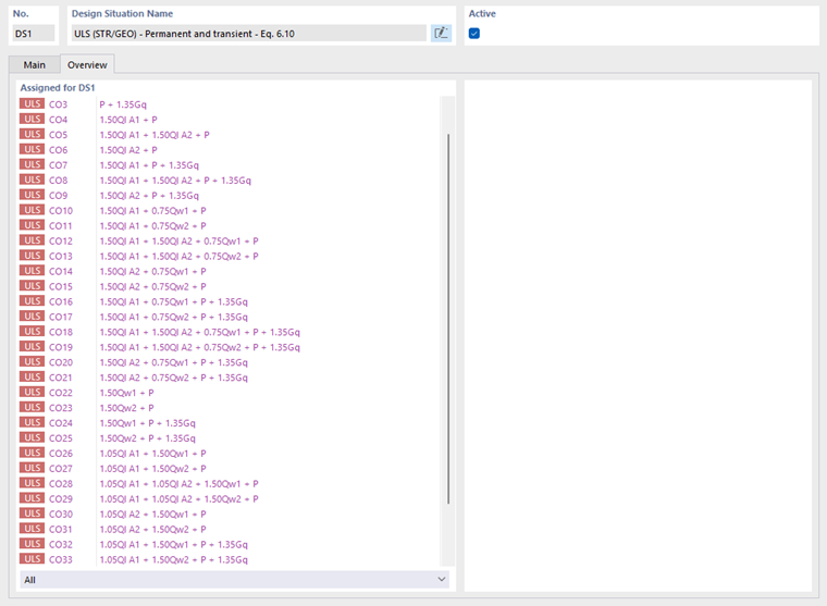
The Overview tab lists all load combinations of the design situation with partial safety factors and combination coefficients. A design situation thus corresponds to an envelope that captures the unfavorable constellations of all included load combinations.