


After importing a CAD file, the problem often arises that connected elements in the structural model have no link. The Rule-Based Coupling Generator facilitates the task of coupling objects: The program creates the connection in the form of rigid members and rigid couplings.

Rule Set
In a so-called 'Rule Set', you define one or more rules for the generation of couplings. Each applies to specific object types. The details of these rules are defined in the Parameters section.
In the 'Active' column, you can control whether a rule is to be applied. When you tick the check box, a row for another rule is automatically added.
The 'Type' plays an important role in creating couplings: It determines between which object types connections are generated. Several options are available for selection in the list.
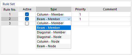
The function of the individual types is described in the table.
| Type | Coupling of Objects |
|---|---|
| Column - Member | Vertical members with members in any position |
| Beam - Member | Horizontal members with members in any position |
| Diagonal - Member | Inclined members with members in any position |
| Diagonal - Node | Inclined members with nodes in vicinity |
| Column - Node | Vertical members with nodes in vicinity |
| Beam - Node | Horizontal members with nodes in vicinity |
The types are based on the following concept: The "source objects" (first designation in the type pair) are connected to the "target objects" (second designation) via the shortest path by Nodal constraints. If necessary, nodes are automatically generated on the target objects.
The order of the rules in the rule set also defines the priorities according to which the objects are coupled. In the 'Priority' column, however, you can change this automatic setting by assigning a lower priority (2) to a rule.
Parameters
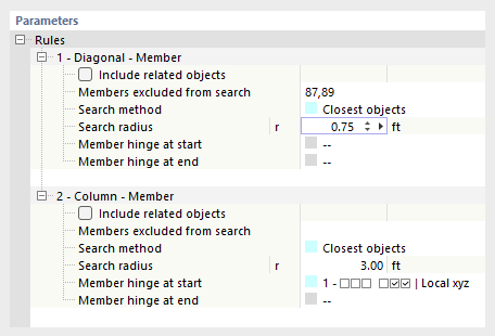
In the lower section, you can specify the details for each rule. They essentially correspond to the specifications that apply to Nodal constraints.
Search Method
Currently, only the 'Closest Objects' option is available. The program searches for which object (member or node) within the defined radius has the smallest distance to the source object. This object is then coupled with a rigid member.
Search Radius
The couplings are only created for objects that are located within a specific radius around the source object.
Nodes/Members/Surfaces Excluded from Search
If certain objects within the search area are not to be coupled, specify the numbers of these target objects. Use the graphical selection option via the button
![]() , which becomes accessible with a click in the input field.
, which becomes accessible with a click in the input field.
Include Belonging Objects
Belonging objects are automatically excluded from the search. These are, for example, integrated objects or definition objects like nodes that are used to define members. When you tick the check box, these objects are also considered in the search.
Member Hinge
By default, the objects are connected in a moment-resistant manner. You can also design the coupling as hinged. To do this, select one of the already defined hinges from the list or define a new hinge type using the button
![]() .
.
Example
- Coupling Type Column - Member
Using the parameters of Rule 1, nodal constraints are created for all vertical members of the model with members that are within a distance of a maximum of 32 cm.


