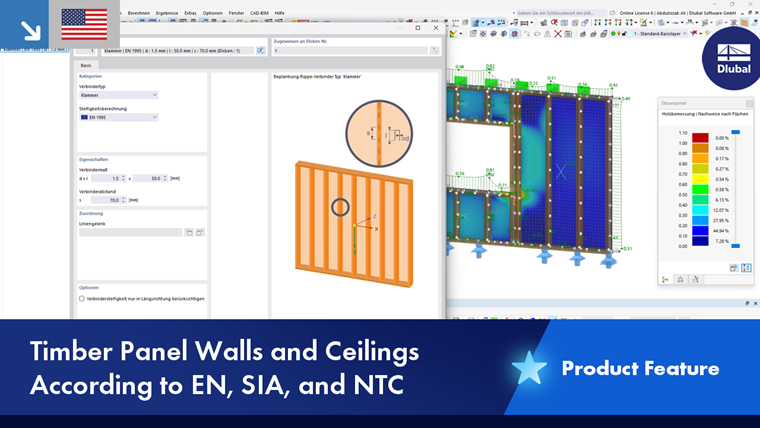
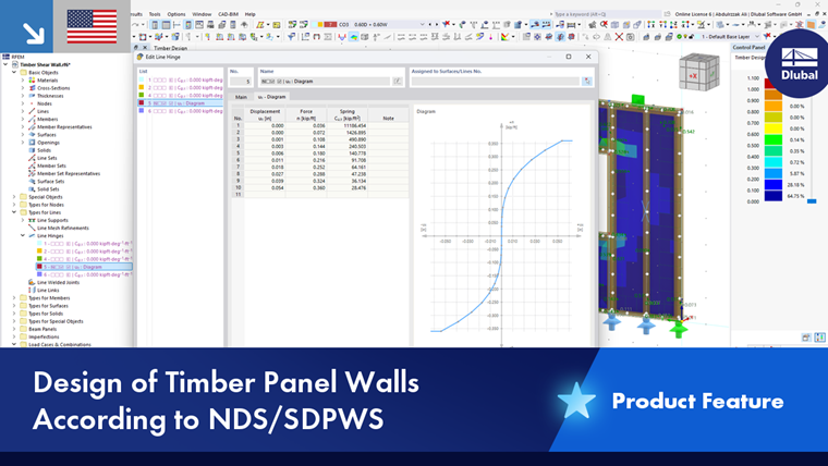
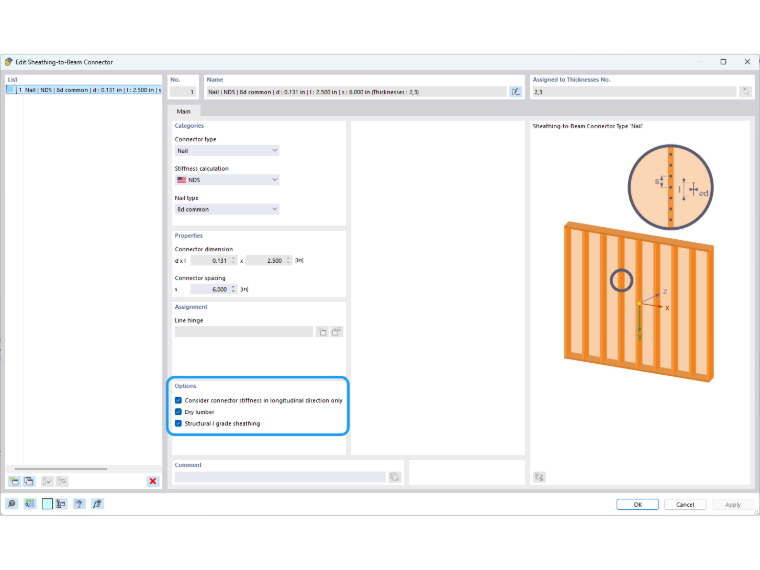
For some standards, the Beam Panels | Connectors tab is available in the “Ultimate Configuration” or “Strength Configuration” dialog box. Here, you can specify basic settings for the design of fasteners and the sheathing of beam panels.
The “Design Parameters” are divided into several subcategories, which vary depending on the design standard. The following sections describe the parameters for these standards:
EN 1995
Surfaces | Beam Panels | Sheathing-to-Beam Connectors
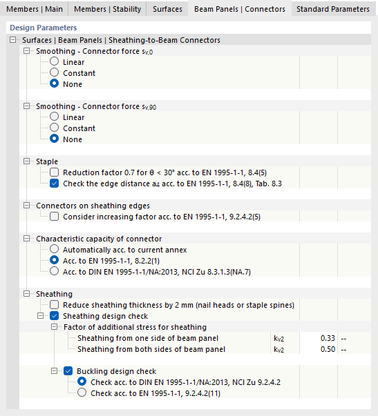
By default, there is no smoothing of the connector forces, so each fastener is designed using its proportional force. If the shear flow is to be “smeared” over the length of the line hinges, select a linear or constant distribution of forces.
The additional subcategories provide setting options for design-relevant parameters of the connectors. The corresponding sections of the standard are specified in each case.
You can reduce the thickness of the sheathing by 2 mm if there is a reduction due to the penetration of nail heads or staple backs. This option is described in the German Annex NCI to 8.3.1.1 (NA.14) and NCI to 8.4 (NA.11). Furthermore, you can easily take into account additional stresses in the sheathing analysis using factors kv2 for single- or double-sided sheathing, for example, for purlin joints.
NDS
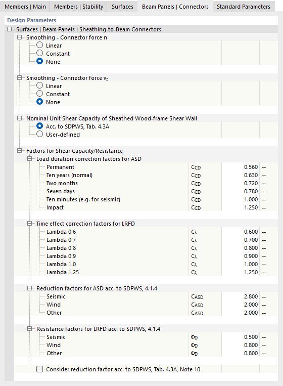
Surfaces | Beam Panels | Sheathing-to-Beam Connectors
By default, there is no smoothing of the connector forces, so each fastener is designed using its proportional force. If you want the shear flow to be “smeared” over the length of the line hinges, select a linear or constant distribution of forces.
The additional subcategories provide setting options for Factors for Shear Capacity/Resistance for ASD and LRFD. There, you can specify correction factors for load duration and time effects, as well as reduction factors for earthquakes or wind and other resistance factors.
CSA
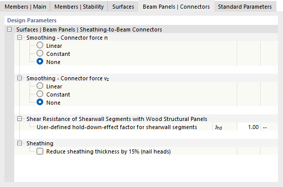
Surfaces | Beam Panels | Sheathing-to-Beam Connectors
By default, there is no smoothing of the connector forces, so each fastener is designed using its proportional force. If you want the shear flow to be “smeared” over the length of the line hinges, select a linear or constant distribution of forces.
If wall segments with fasteners do not resist all uplift forces—multiplied by a safety factor—based on overturning, the hold-down factor Jhd shall be reduced according to [1] Section 11.5.5.3.
Optionally, the thickness of the sheathing may be reduced by 15% according to [1], Section 11.3.2.3 to take into account the maximum penetration of the nail heads. The reduced thickness of the sheathing and the penetration of the nails are specified in the design check details following the calculation.